Ir para o conteúdo principal

HKC P774A LCD screen Replacement

O que você precisa

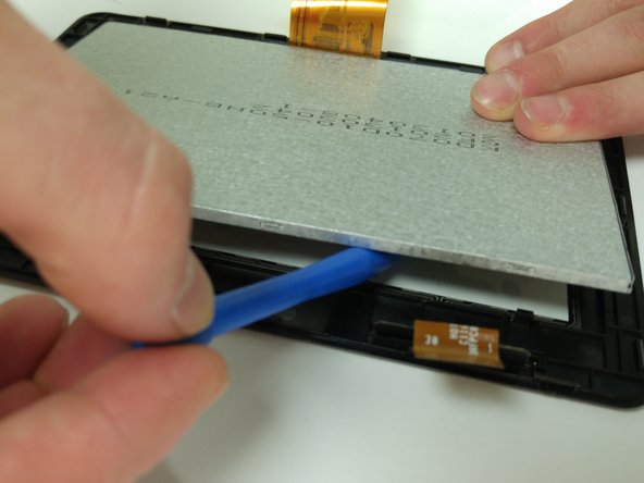
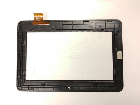
  1. HKC P774A LCD screen Replacement, Digitizer: passo 1, imagem 1 %32 HKC P774A LCD screen Replacement, Digitizer: passo 1, imagem 2 %32 HKC P774A LCD screen Replacement, Digitizer: passo 1, imagem 3 %32
    • Insert the flat end of the spudger into the side of the device

    • This will create a gap between the device and screen housing.

    • Insert the plastic opening tool into this gap and move it along this gap.

    • Make sure not to bent the digitizer during this step.

    • The screen housing and device will now be separated.

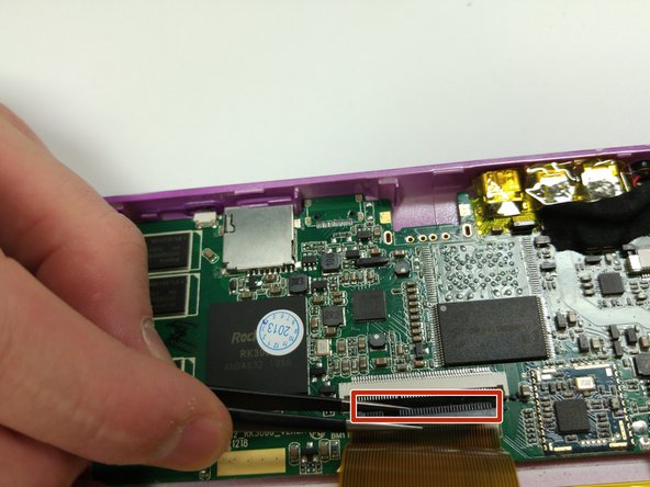
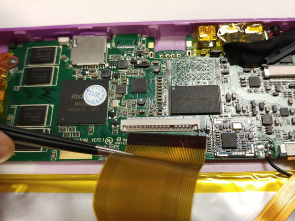
  2. HKC P774A LCD screen Replacement: passo 2, imagem 1 %32 HKC P774A LCD screen Replacement: passo 2, imagem 2 %32 HKC P774A LCD screen Replacement: passo 2, imagem 3 %32
    • Once the digitizer has been been removed from the body, disconnect the digitizer band from the motherboard.

    • Two small black pins (circled in red) will need to be unlocked.

    • Unlock the pins by pulling them outward with the tweezers.

    • Make sure the pins are released entirely before attempting to remove the band.

    • Remove the band using the tweezers.

  3. HKC P774A LCD screen Replacement: passo 3, imagem 1 %32 HKC P774A LCD screen Replacement: passo 3, imagem 2 %32 HKC P774A LCD screen Replacement: passo 3, imagem 3 %32
    • Once the digitizer has been disconnected from the motherboard, the LCD screen must be removed from the digitizer.

    • Push open the tabs (circled in red) using the flat end of the plastic spudger.

    • Be sure not to bend the digitizer while prying.

    • Continue to release all tabs while continuing to pry the LCD away from the digitizer.

  4. HKC P774A LCD screen Replacement, LCD screen: passo 4, imagem 1 %32 HKC P774A LCD screen Replacement, LCD screen: passo 4, imagem 2 %32 HKC P774A LCD screen Replacement, LCD screen: passo 4, imagem 3 %32
    • Once the digitizer has been removed, the LCD can be disconnected from the motherboard.

    • Use the tweezers to unlock the black pins (outlined in red) that connect the LCD band to the motherboard.

    • Once the pins have been removed, pull the band out using the tweezers.

    • Make sure not to damage the band when removing the pins.

Conclusão

To reassemble your device, follow these instructions in reverse order.

Uma outra pessoa concluiu este guia.

Sean McCauley

Membro desde: 10/26/15

512 Reputação

Autoria de 4 guias

Equipe

Montana Tech, Team 10-1, Shirk Fall 2015 Membro de Montana Tech, Team 10-1, Shirk Fall 2015

MTUM-SHIRK-F15S10G1

Membros da 4

Autoria de 8 guias

0 comentários

Adicione um comentário

Exibir estatísticas:

Últimas 24 horas: 0

Últimos 7 dias: 0

Últimos 30 dias: 1

Duração total: 326