Esta versão pode conter edições incorretas. Mude para o último instantâneo verificado.
O que você precisa
-
Este passo não foi traduzido. Ajude a traduzi-lo
-
Heat an iOpener and apply it to the bottom of the phone for one minute.
-
-
Este passo não foi traduzido. Ajude a traduzi-lo
-
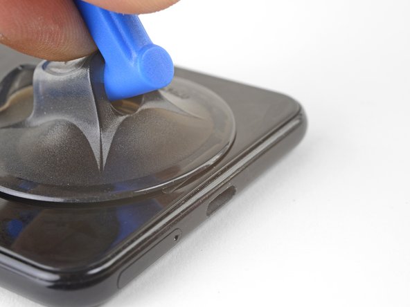
Apply a suction cup to the heated bottom edge of the back cover.
-
Lift on the suction cup with strong, steady force to create a gap.
-
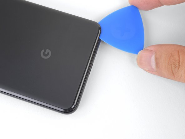
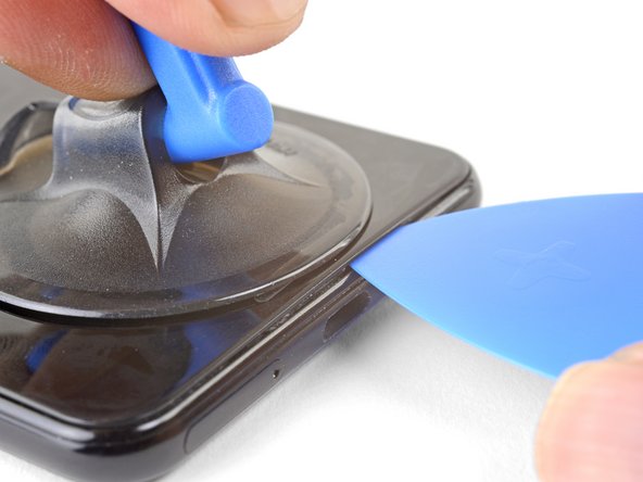
Insert an opening pick into the gap.
-
-
Este passo não foi traduzido. Ajude a traduzi-lo
-
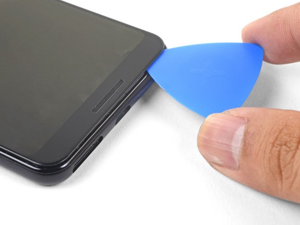
Slice the adhesive along the bottom edge of the phone and around the right corner.
-
Leave a pick in the bottom edge to prevent the adhesive from re-sealing.
-
-
Este passo não foi traduzido. Ajude a traduzi-lo
-
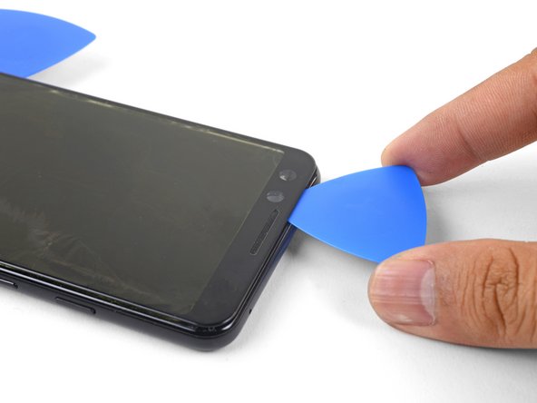
Heat the right edge with an iOpener and continue slicing the adhesive with an opening pick.
-
-
Este passo não foi traduzido. Ajude a traduzi-lo
-
Continue heating and slicing through the rest of the phone perimeter. Leave a pick in each edge to prevent the adhesive from resealing.
-
-
Este passo não foi traduzido. Ajude a traduzi-lo
-
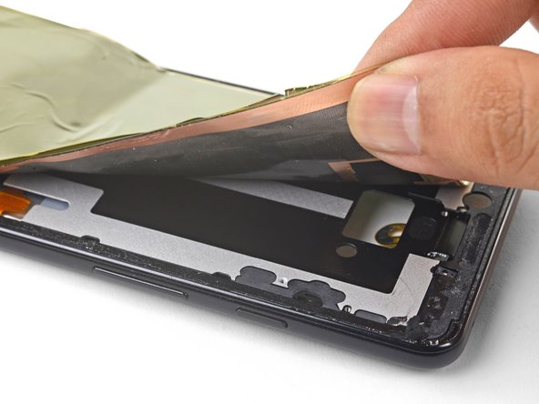
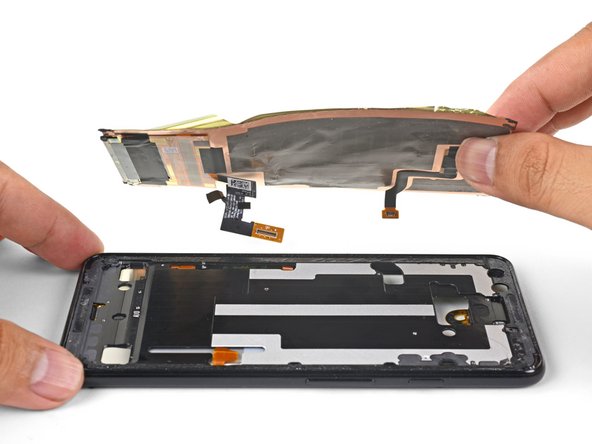
Once you have sliced around the perimeter of the phone, carefully lift the left edge of the back cover.
-
Flip the back cover along its long axis and rest it so that the fingerprint sensor cable is not strained.
-
-
Este passo não foi traduzido. Ajude a traduzi-lo
-
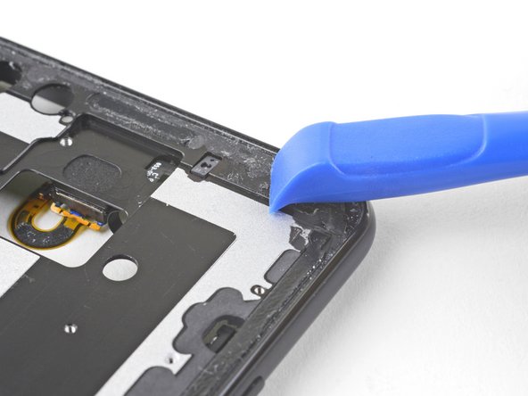
Remove the two 4.1 mm-long Phillips screws securing the fingerprint connector bracket.
-
-
Este passo não foi traduzido. Ajude a traduzi-lo
-
Use the point of a spudger to slide the fingerprint connector bracket out from under the NFC coil.
-
Remove the fingerprint connector bracket.
-
-
Este passo não foi traduzido. Ajude a traduzi-lo
-
Use the point of a spudger to pry up and disconnect the fingerprint connector from its socket.
-
-
Este passo não foi traduzido. Ajude a traduzi-lo
-
Remove the five Phillips screws securing the wireless charging coil:
-
Two 1.9 mm screws
-
Two 4.2 mm screws
-
One 4.3 mm screw
-
-
Este passo não foi traduzido. Ajude a traduzi-lo
-
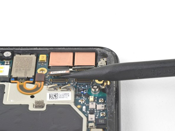
Use the point of a spudger to pry up and disconnect the battery press connector from its socket near the right edge of the phone.
-
-
Este passo não foi traduzido. Ajude a traduzi-lo
-
Remove the two screws securing the camera bracket:
-
One 4.1 mm Phillips screw
-
One 4 mm standoff screw
-
Remove the camera bracket.
-
-
-
Este passo não foi traduzido. Ajude a traduzi-lo
-
Use the point of a spudger to pry up and disconnect the connector for the camera(s) you are replacing.
-
-
Este passo não foi traduzido. Ajude a traduzi-lo
-
Insert the point of a spudger behind the edge of the camera module and pry up to loosen it from the frame.
-
-
Este passo não foi traduzido. Ajude a traduzi-lo
-
Use a pair of blunt nose tweezers to remove the camera(s).
-
-
Este passo não foi traduzido. Ajude a traduzi-lo
-
Use the point of a spudger to pry up and disconnect the loudspeaker connector from its motherboard socket near the right edge of the phone.
-
-
Este passo não foi traduzido. Ajude a traduzi-lo
-
Remove the following four Phillips screws:
-
One 1.9 mm screw
-
One 4.3 mm screw
-
Two 4.3 mm screws with thinner shanks
-
Remove the tiny grounding clip from the left screw hole. Be careful not to lose it.
-
Remove the small plastic insert from the right side of the USB-C port.
-
-
Este passo não foi traduzido. Ajude a traduzi-lo
-
Insert the point of a spudger under the bottom right corner of the loudspeaker.
-
Pry up to loosen the loudspeaker from the phone.
-
-
Este passo não foi traduzido. Ajude a traduzi-lo
-
Insert the point of a spudger under the top left corner of the loudspeaker.
-
Pry up to loosen the loudspeaker.
-
-
Este passo não foi traduzido. Ajude a traduzi-lo
-
Insert the flat end of the spudger under the top edge of the loudspeaker, towards the left edge.
-
Pry up to loosen the loudspeaker.
-
-
Este passo não foi traduzido. Ajude a traduzi-lo
-
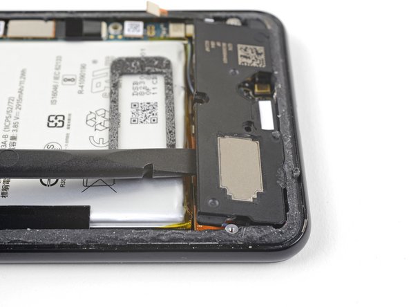
Remove the loudspeaker.
-
If it is in good condition, you can re-use the gasket. Make sure that the gasket does not cover the exit hole.
-
If the gasket is pulled out of place, remove it and replace the adhesive with a pre-cut strip or Tesa tape.
-
-
Este passo não foi traduzido. Ajude a traduzi-lo
-
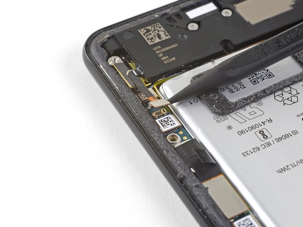
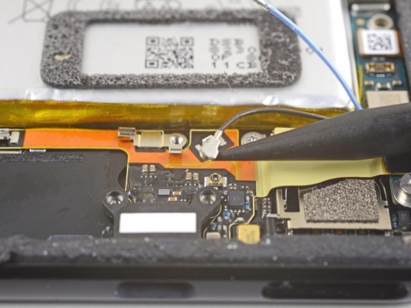
Use the point of a spudger to pry up and disconnect the blue antenna cable from its socket on the charging assembly.
-
-
Este passo não foi traduzido. Ajude a traduzi-lo
-
Use the point of a spudger to carefully pry up and release the blue antenna cable from its grounding clips.
-
-
Este passo não foi traduzido. Ajude a traduzi-lo
-
Use the point of a spudger to pry up and disconnect the black antenna cable from its socket near the USB-C port.
-
-
Este passo não foi traduzido. Ajude a traduzi-lo
-
Carefully de-route both antenna cables and move them away from the charging assembly.
-
-
Este passo não foi traduzido. Ajude a traduzi-lo
-
Use the point of a spudger to pry up and disconnect the charging assembly's connector from its motherboard socket, near the right edge of the phone.
-
Carefully peel the flex cable from the top of the SIM card reader.
-
-
Este passo não foi traduzido. Ajude a traduzi-lo
-
Use the flat end of a spudger to carefully pry up the black tape holding the display flex cable in place, near the right edge of the phone.
-
Use the flat end of a spudger to pry up and disconnect the display connector from the motherboard.
-
-
Este passo não foi traduzido. Ajude a traduzi-lo
-
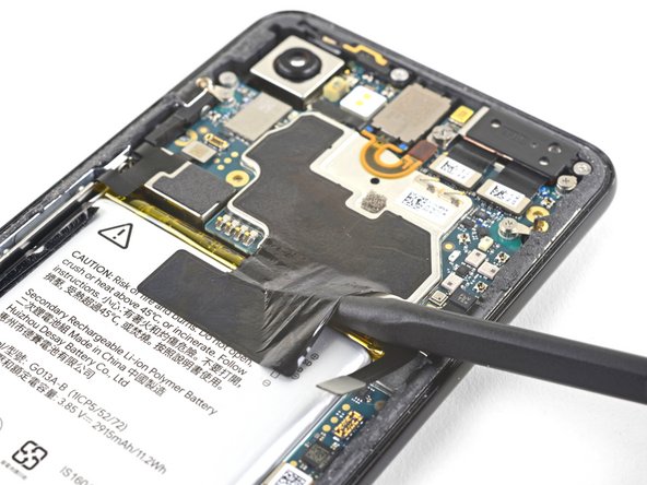
Slide the point of a spudger in the crevice underneath the black tape bridging across the battery and the motherboard.
-
Slide the spudger along the crevice to pry up the tape from the battery side.
-
Carefully peel the tape from the battery and fold it out of the way.
-
-
Este passo não foi traduzido. Ajude a traduzi-lo
-
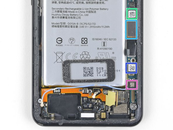
Use a spudger to pry up and disconnect the following seven press-fit connectors from their motherboard sockets:
-
External buttons connector
-
Top microphone connector
-
Earpiece connector
-
Left squeeze sensor connector
-
Screen connector
-
Right squeeze sensor connector
-
SIM tray connector
-
-
Este passo não foi traduzido. Ajude a traduzi-lo
-
Use the flat of a spudger to carefully pry up and bend the earpiece speaker's flex cable upwards, out of the way of the motherboard.
-
-
Este passo não foi traduzido. Ajude a traduzi-lo
-
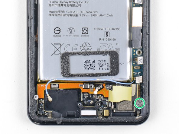
Remove the six screws securing the motherboard in place:
-
One 4.2 mm Phillips screw
-
Three 1.9 mm Phillips screws
-
One 4.3 mm Phillips screw
-
One 3.83 mm standoff screw
-
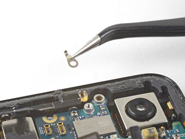
Remove and retain the three small metal grounding clips.
-
-
Este passo não foi traduzido. Ajude a traduzi-lo
-
Carefully remove the antenna bracket from the top left edge of the phone.
-
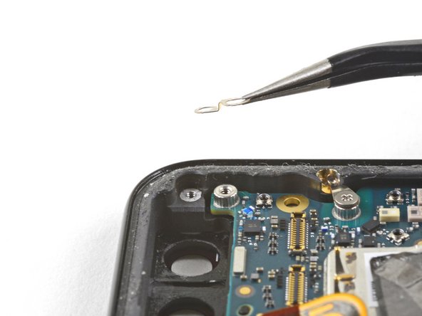
Orient the clips such that the silver side is facing upwards.
-
The teardrop shaped clips should have their points facing towards the phone edge.
-
The double-holed clip dips downwards towards the frame's top-right screw hole.
-
-
Este passo não foi traduzido. Ajude a traduzi-lo
-
Insert the point of a spudger near the top left corner of the motherboard, right below the rear-facing camera.
-
Pry up gently to loosen the motherboard, bending all flex cables away to accommodate for the movement.
-
If the motherboard feels firmly seated, check for any flex cables or screws that may still be connected.
-
-
Este passo não foi traduzido. Ajude a traduzi-lo
-
Insert the spudger underneath the top edge of the motherboard and carefully pry up to loosen the motherboard.
-
-
Este passo não foi traduzido. Ajude a traduzi-lo
-
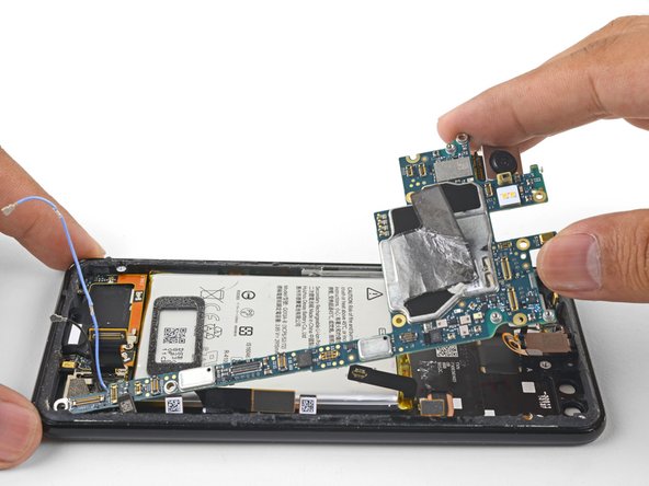
Lift the left edge of the motherboard and carefully swing upwards it towards the right. Carefully push any press connectors snagging the motherboard out of the way.
-
-
Este passo não foi traduzido. Ajude a traduzi-lo
-
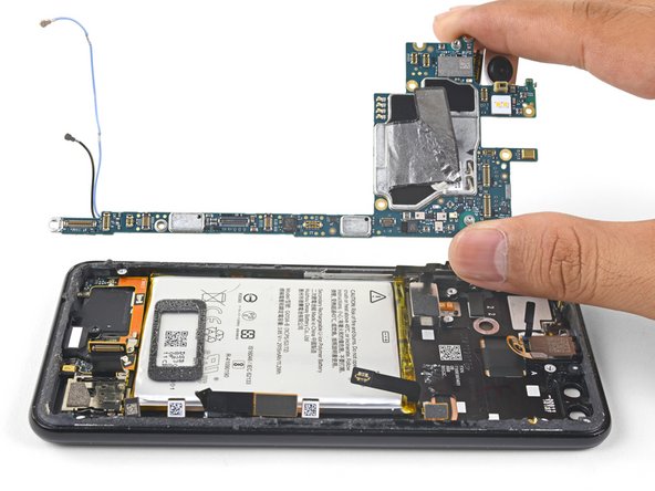
Carefully lift the top end of the motherboard away from the frame.
-
Remove the motherboard.
-
-
Este passo não foi traduzido. Ajude a traduzi-lo
-
Apply a heated iOpener to the bottom edge of the screen for a minute.
-
Place a suction cup near the bottom edge of the screen, near the USB-C port.
-
Lift on the suction cup with strong, steady force to create a gap.
-
You can also try heating and pulling up a long edge of the phone to gain access.
-
Insert an opening pick into the gap.
-
-
Este passo não foi traduzido. Ajude a traduzi-lo
-
Slide the pick along the bezel to slice through the adhesive.
-
-
Este passo não foi traduzido. Ajude a traduzi-lo
-
Continue heating edges with an iOpener and slicing the adhesive with an opening pick, until you've sliced through all of the adhesive.
-
-
Este passo não foi traduzido. Ajude a traduzi-lo
-
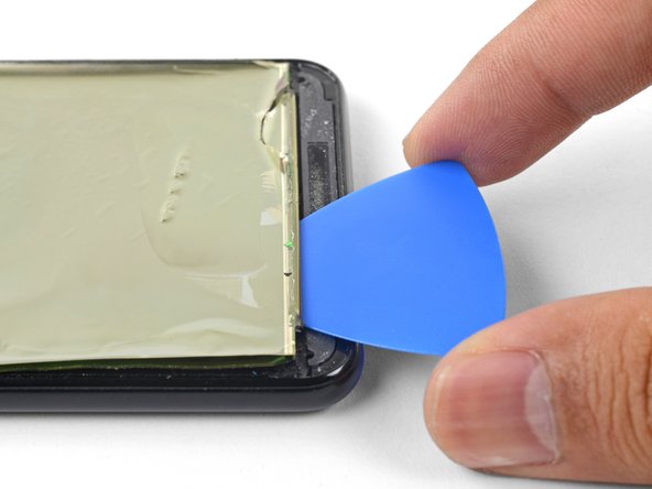
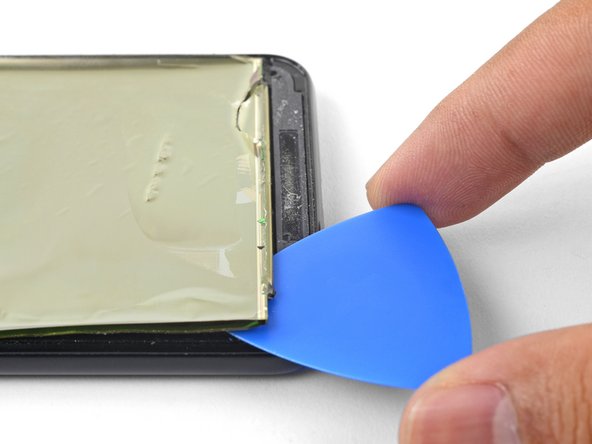
Insert an opening pick into the seam between the phone frame and the bottom edge of the screen remains.
-
Pry along the edge to loosen the screen from the frame.
-
-
Este passo não foi traduzido. Ajude a traduzi-lo
-
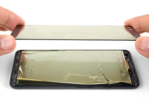
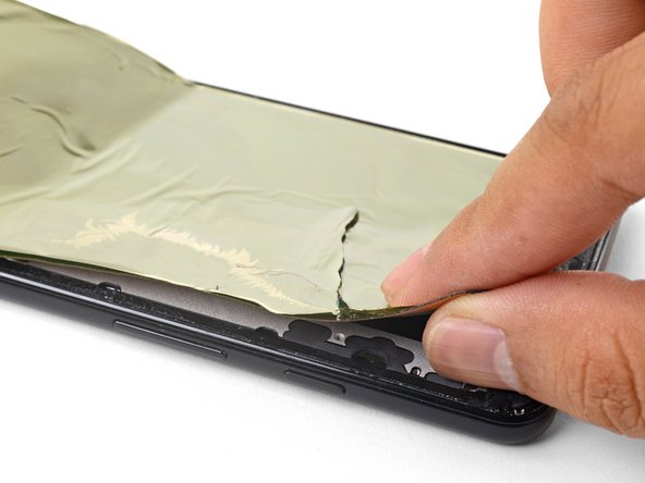
Continue applying heat and slicing along a screen edge until you've loosened enough material to be grasped with your fingers.
-
Grasp the edge with your fingers and slowly pull the screen remains away from the phone frame.
-
-
Este passo não foi traduzido. Ajude a traduzi-lo
-
Thread the screen cable and digitizer cable out of their cutouts, then remove the display.
-
Clean all adhesive residue from the phone frame. Adhesive that's left behind may apply uneven pressure against the replacement screen and potentially damage it.
-
Apply a pre-cut adhesive, or double-sided tape to the phone frame's perimeter.
-
Peel all plastic liners from the back of the replacement screen to expose the adhesive.
-
Carefully thread the screen cable and the digitizer cable through the phone frame's cutouts.
-
Lay the screen onto the frame and place some books on top for an hour to help the screen adhesive bond to the frame.
-


Cancelar: não concluí este guia.
26 outras pessoas executaram este guia.


29 comentários
To change only the screen glass… Do you have to disassemble the whole phone or just steps 39 to 42?
Thanks
Hi Adrián,
The OLED is bonded to the screen glass. Unlike LCDs, trying to remove the glass only will most likely destroy the OLED screen.
How to differentiate between a pre-mounted and a non pre-mounted display? I don’t want to order the wrong part, hence the question.
The pre-mounted part will come with the frame, which is the majority of the phone body. The screen is already stuck affixed to the frame, but you would have to transfer everything else onto it. The display only part looks like a thin panel with adhesive on the back. It would look like this part.
When buying a replacement screen do I need to buy it with a frame?