Esta versão pode conter edições incorretas. Mude para o último instantâneo verificado.
O que você precisa
-
Este passo não foi traduzido. Ajude a traduzi-lo
-
Insert a SIM card eject tool or a paperclip into the small hole in the SIM card tray, located on the left edge of the phone, opposite of the power and volume buttons.
-
Press firmly to eject the tray.
-
-
Este passo não foi traduzido. Ajude a traduzi-lo
-
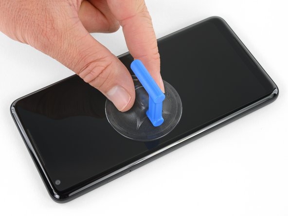
Apply a suction cup as close to the SIM slot edge of the phone as you can while avoiding the curved edge.
-
-
Este passo não foi traduzido. Ajude a traduzi-lo
-
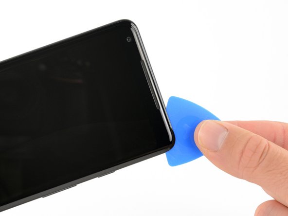
Pull up on the suction cup with firm, constant pressure and insert an opening pick between the front panel and rear case.
-
-
Este passo não foi traduzido. Ajude a traduzi-lo
-
Do not insert the pick more than 0.25 inches (6 mm) into the bottom edge of the phone. If the pick contacts the folded portion of the OLED panel, it can damage the display.
-
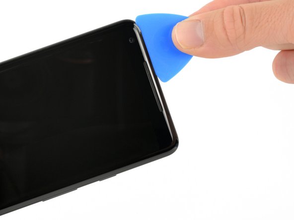
Do not cut along the left edge; there are delicate display cables that can be damaged.
-
Only make very shallow cuts in the upper left corner; prying deeply can damage the front-facing camera.
-
-
Este passo não foi traduzido. Ajude a traduzi-lo
-
Slide the opening pick down the right side of the phone to separate the display adhesive.
-
-
Este passo não foi traduzido. Ajude a traduzi-lo
-
Slide the opening pick around the lower-right corner and along the bottom edge of the phone.
-
-
Este passo não foi traduzido. Ajude a traduzi-lo
-
Reinsert the flat edge of the pick at the top-right corner of the phone, and slide it around the corner and the top edge of the phone.
-
-
-
Este passo não foi traduzido. Ajude a traduzi-lo
-
Gently lift the display from the right side of the phone, opening it like a book.
-
Carefully lay the display flat on the table next to the rest of the phone, keeping it close to the phone to avoid straining the display and digitizer cables.
-
-
Este passo não foi traduzido. Ajude a traduzi-lo
-
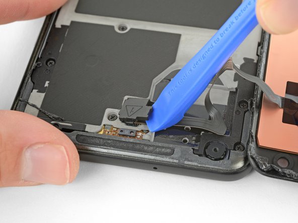
Use the corner of an opening tool to pry up and unclip on the lower edge of the digitizer cable connector cover.
-
Remove the connector cover.
-
-
Este passo não foi traduzido. Ajude a traduzi-lo
-
Use the point of a spudger to lift the digitizer cable connector up and out of its socket on the motherboard.
-
-
Este passo não foi traduzido. Ajude a traduzi-lo
-
Use tweezers to remove any tape from the display connector cover.
-
-
Este passo não foi traduzido. Ajude a traduzi-lo
-
Insert the point of a spudger into the small hole on the edge of the display connector cover.
-
Use the spudger to pry the cover out of its recess.
-
Remove the connector cover.
-
-
Este passo não foi traduzido. Ajude a traduzi-lo
-
Use the flat edge of a spudger to lift the display cable connector up from its socket.
-
Remove the display.
-
-
Este passo não foi traduzido. Ajude a traduzi-lo
-
Remove eleven 3.8 mm Phillips screws securing the midframe.
-
-
Este passo não foi traduzido. Ajude a traduzi-lo
-
Insert an opening tool into the notch in the midframe near the volume buttons and pry the midframe up and away from the rest of the phone.
-
Remove the midframe.
-
-
Este passo não foi traduzido. Ajude a traduzi-lo
-
Use the flat end of a spudger to disconnect the battery connector.
-
-
Este passo não foi traduzido. Ajude a traduzi-lo
-
Use the point of a spudger to disconnect the front-facing camera connector.
-
-
Este passo não foi traduzido. Ajude a traduzi-lo
-
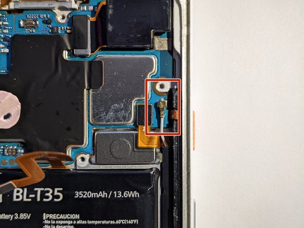
Use the flat end of a spudger to disconnect the right Active Edge sensor connector.
-
Disconnect the antenna cable.
-
-
Este passo não foi traduzido. Ajude a traduzi-lo
-
Use the point of a spudger to disconnect the fingerprint sensor connector.
-
-
Este passo não foi traduzido. Ajude a traduzi-lo
-
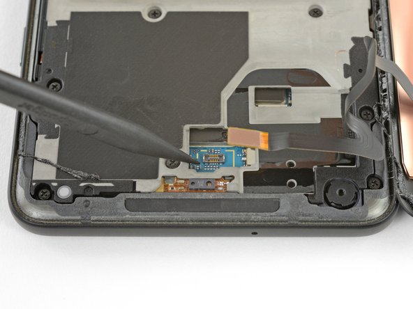
Use the flat end of a spudger to disconnect the left Active Edge sensor connector.
-
-
Este passo não foi traduzido. Ajude a traduzi-lo
-
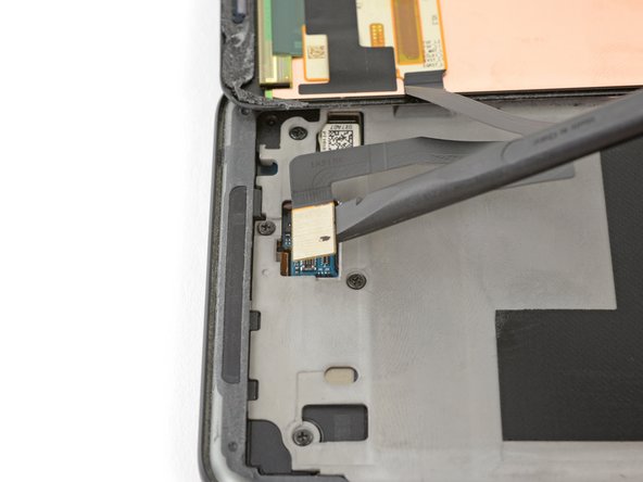
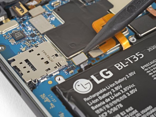
Use the flat end of a spudger to disconnect the charging assembly connector.
-
-
Este passo não foi traduzido. Ajude a traduzi-lo
-
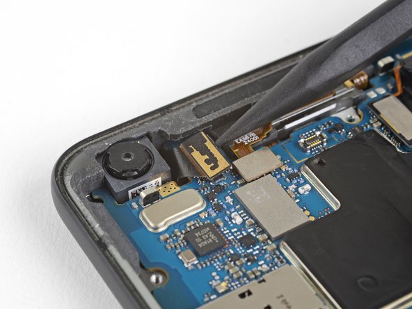
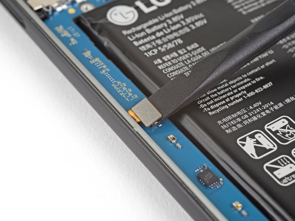
Use the point of a spudger to disconnect the front-facing sensor assembly connector.
-
-
Este passo não foi traduzido. Ajude a traduzi-lo
-
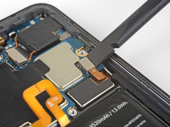
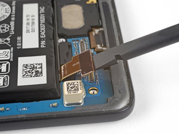
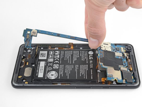
Make sure all the cables and connectors are clear of the board, and use the flat edge of a spudger to gently lift the bottom of the motherboard.
-
Holding the wide part of the motherboard near the SIM card slot, carefully slide the board toward the bottom of the phone while lifting it out of the phone.
-
Remove the motherboard.
-
Try to keep the phone flat with the battery facing up after you remove the motherboard, as the front-facing camera can fall out of the phone case very easily.
-


Cancelar: não concluí este guia.
7 outras pessoas executaram este guia.

Um comentário
You jump from “eject the SIM tray” to “the display is already removed, check for speaker grills” … WTF?!