Ir para o conteúdo principal

GE 7-4836B Alarm Clock AM-FM Radio LCD Panel Replacement

O que você precisa

  1. GE 7-4836B Alarm Clock AM-FM Radio LCD Panel Replacement, Battery Compartment Cover: passo 1, imagem 1 %32 GE 7-4836B Alarm Clock AM-FM Radio LCD Panel Replacement, Battery Compartment Cover: passo 1, imagem 2 %32 GE 7-4836B Alarm Clock AM-FM Radio LCD Panel Replacement, Battery Compartment Cover: passo 1, imagem 3 %32
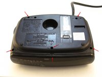
    • Find the battery compartment on the bottom of the clock radio.

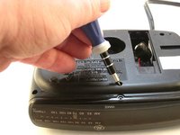
    • Using your thumb, push the compartment cover latch toward the battery.

    • With the latch pushed in, pull the compartment cover upward to remove it..

  2. GE 7-4836B Alarm Clock AM-FM Radio LCD Panel Replacement, Battery: passo 2, imagem 1 %32 GE 7-4836B Alarm Clock AM-FM Radio LCD Panel Replacement, Battery: passo 2, imagem 2 %32
    • Lift the battery from the compartment.

    • Pull the battery up and gently disconnect it from the battery connector.

  3. GE 7-4836B Alarm Clock AM-FM Radio LCD Panel Replacement, Screws: passo 3, imagem 1 %32 GE 7-4836B Alarm Clock AM-FM Radio LCD Panel Replacement, Screws: passo 3, imagem 2 %32
    • Using a Phillips #00 Screwdriver, unscrew the six 12mm screws from around the bottom of the clock radio.

  4. GE 7-4836B Alarm Clock AM-FM Radio LCD Panel Replacement, LCD Cover: passo 4, imagem 1 %32
    • Gently pull the liquid crystal display (LCD) cover off.

  5. GE 7-4836B Alarm Clock AM-FM Radio LCD Panel Replacement, Clock Radio: passo 5, imagem 1 %32 GE 7-4836B Alarm Clock AM-FM Radio LCD Panel Replacement, Clock Radio: passo 5, imagem 2 %32
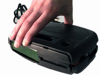
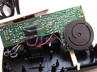
    • Lift the top off. Two gray, plastic internal pieces will fall out when you do this; set them aside.

  6. GE 7-4836B Alarm Clock AM-FM Radio LCD Panel Replacement, Battery Wires Wire Tie: passo 6, imagem 1 %32 GE 7-4836B Alarm Clock AM-FM Radio LCD Panel Replacement, Battery Wires Wire Tie: passo 6, imagem 2 %32
    • Using the wire cutters, carefully cut the plastic wire tie.

  7. GE 7-4836B Alarm Clock AM-FM Radio LCD Panel Replacement, Hot Melt Glue: passo 7, imagem 1 %32 GE 7-4836B Alarm Clock AM-FM Radio LCD Panel Replacement, Hot Melt Glue: passo 7, imagem 2 %32 GE 7-4836B Alarm Clock AM-FM Radio LCD Panel Replacement, Hot Melt Glue: passo 7, imagem 3 %32
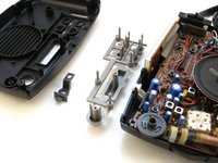
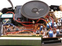
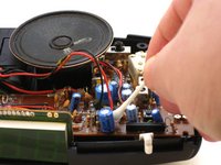
    • Follow the wires to find where they connect to the printed circuit board (PCB). At the area of connect, two spots will be marked "DC+ and "DC-."

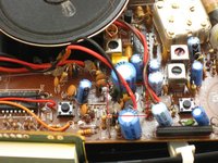
    • Apply the rubbing alcohol to the cotton swab end. Rub the end of the cotton swab on hot melt glue and wait for 30 seconds, then apply the alcohol to the hot melt glue again.

    • Use the tweezers to grab the softened hot melt glue. Pull the hot melt glue off of the clock radio.

  8. GE 7-4836B Alarm Clock AM-FM Radio LCD Panel Replacement, Speaker: passo 8, imagem 1 %32
    • Grip the speaker.

    • Lift the speaker from the holder.

  9. GE 7-4836B Alarm Clock AM-FM Radio LCD Panel Replacement, Two Screws: passo 9, imagem 1 %32 GE 7-4836B Alarm Clock AM-FM Radio LCD Panel Replacement, Two Screws: passo 9, imagem 2 %32
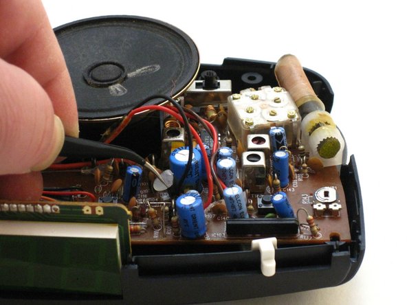
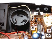
    • Locate the two 6mm screws on the PCB.

    • Using a Phillips #0 Screwdriver, unscrew the two 6 mm screws from the PCB.

  10. GE 7-4836B Alarm Clock AM-FM Radio LCD Panel Replacement, LCD Connection to PCB: passo 10, imagem 1 %32 GE 7-4836B Alarm Clock AM-FM Radio LCD Panel Replacement, LCD Connection to PCB: passo 10, imagem 2 %32
    • Raise the PCB.

    • Locate the LCD connection to the PCB.

  11. GE 7-4836B Alarm Clock AM-FM Radio LCD Panel Replacement, Hot Melt Glue: passo 11, imagem 1 %32 GE 7-4836B Alarm Clock AM-FM Radio LCD Panel Replacement, Hot Melt Glue: passo 11, imagem 2 %32
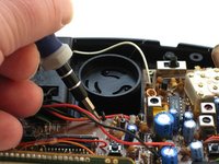
    • Apply the rubbing alcohol to the cotton swab end. Rub the end on the hot melt glue and wait for 30 seconds, then apply the alcohol to the hot melt again.

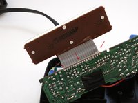
    • Using the tweezers, pull the hot melt glue from the LCD connector.

  12. GE 7-4836B Alarm Clock AM-FM Radio LCD Panel Replacement, Heated Soldering Iron: passo 12, imagem 1 %32
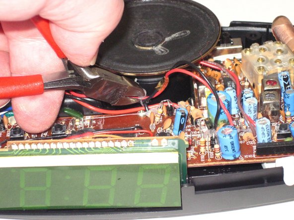
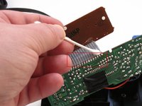
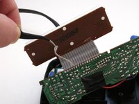
    • Carefully apply the heated soldering iron on each of the 17 ribbon cable pin solders (first one as shown). Continue until the ribbon cable is detached.

Conclusão

To reassemble your device, follow these instructions in reverse order.

2 outras pessoas executaram este guia.

Dominick Giguere

Membro desde: 10/28/14

848 Reputação

Autoria de 6 guias

Um comentário

hello sir ,

i would like to know the voltage details of the transformer has two sec windings

120 v ac primary i want the sec voltage details

thank you

Ganesh kumar

ganeshbglr@gmail.com

ganeshbglr - Responder

Adicione um comentário

Exibir estatísticas:

Últimas 24 horas: 0

Últimos 7 dias: 1

Últimos 30 dias: 13

Duração total: 1,629