Esta versão pode conter edições incorretas. Mude para o último instantâneo verificado.
O que você precisa
-
Este passo não foi traduzido. Ajude a traduzi-lo
-
Unscrew a total of 6 4.45 mm phillips head screws using a #00 phillips head screwdriver.
-
There are 2 screws on the left side (when looking at the front of the camera).
-
There are 3 screws on the bottom
-
There is 1 screw on the right side
-
-
Este passo não foi traduzido. Ajude a traduzi-lo
-
Turn to the bottom of the camera.
-
Open the memory card cover by sliding the "CARD/BATT." button up, and then pulling the cover to the left.
-
-
Este passo não foi traduzido. Ajude a traduzi-lo
-
This is what the SD card/battery compartment looks like when opened.
-
Remove one 4.45mm phillips head screw from the SD card/battery compartment using a #00 phillips head screwdriver.
-
-
Este passo não foi traduzido. Ajude a traduzi-lo
-
Gently remove the front cover away from the camera body.
-
-
-
Este passo não foi traduzido. Ajude a traduzi-lo
-
The camera should look like this once the front cover is removed.
-
-
Este passo não foi traduzido. Ajude a traduzi-lo
-
Start from the battery compartment and remove the back cover.
-
Remove the connecting ribbon from the body of the camera using a pair of tweezers.
-
-
Este passo não foi traduzido. Ajude a traduzi-lo
-
Once the ribbon connecting the back cover is removed, the back of the camera body should look like this.
-
-
Este passo não foi traduzido. Ajude a traduzi-lo
-
Remove 2 4.35mm phillips head screws from around the LCD screen using a #00 phillips head screwdriver.
-
Loosen the black ribbon clamp using an iPod opening tool
-
Release the LCD screen by removing the ribbon from the body of the camera.
-
-
Este passo não foi traduzido. Ajude a traduzi-lo
-
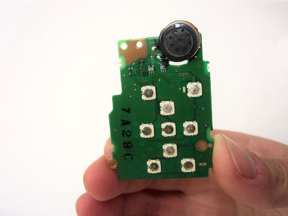
Unscrew 2 3.35mm phillips head screw from the face of the function key motherboard using a #00 phillips head screwdriver.
-
-
Este passo não foi traduzido. Ajude a traduzi-lo
-
Release the black ribbon clamp attached to the back of the motherboard using an iPod opening tool to lift the clamp.
-
Remove the ribbon connecting the function key motherboard from the body of the camera using tweezers.
-
The function key motherboard has the SD card reader attached to the back. The motherboard and SD card combination should be replaced.
-


Cancelar: não concluí este guia.
Uma outra pessoa concluiu este guia.
Equipe

Cal Poly, Team 8-6, Regan Spring 2011 Membro de Cal Poly, Team 8-6, Regan Spring 2011
CPSU-REGAN-S11S8G6
Membros da 4
Autoria de 22 guias