Esta versão pode conter edições incorretas. Mude para o último instantâneo verificado.
O que você precisa
-
Este passo não foi traduzido. Ajude a traduzi-lo
-
Use a Phillips #0 screwdriver to remove the four 21.7mm screws holding the back panel to the frame.
-
-
Este passo não foi traduzido. Ajude a traduzi-lo
-
Once the screws are out, use a plastic opening tool or spudger to pry the top of the back panel open. There may be some resistance, but it will eventually pry loose.
-
-
Este passo não foi traduzido. Ajude a traduzi-lo
-
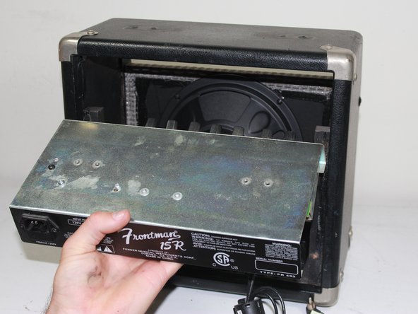
Once the top is separated, use your hand to remove the back panel from the unit.
-
-
Este passo não foi traduzido. Ajude a traduzi-lo
-
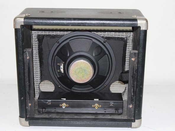
There will be two black wires connecting the top mounting bracket to the reverb box at the bottom of the unit. Label the wires to prevent crossing upon re-installation, then unplug the wires from the reverb box.
-
-
-
Este passo não foi traduzido. Ajude a traduzi-lo
-
Label and unplug the two red wires connecting the mounting bracket to the speaker by pulling them off the nodes.
-
-
Este passo não foi traduzido. Ajude a traduzi-lo
-
Use a Phillips #1 screwdriver to unscrew the four 36.4 mm screws holding the mounting bracket to the top of the amp.
-
-
Este passo não foi traduzido. Ajude a traduzi-lo
-
Pull the mounting bracket free from the frame. It may be wedged in very snug, in which case, use a plastic opening tool/spudger to pry it loose from the front.
-
-
Este passo não foi traduzido. Ajude a traduzi-lo
-
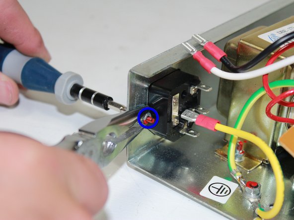
Before disconnecting the wires, label, make note of, or memorize each wire according to where it connects to the power input jack.
-
Disconnect the wire connectors from the back of the input jack by pulling them away from the jack.
-
-
Este passo não foi traduzido. Ajude a traduzi-lo
-
Use Philips #1 Screwdriver to unscrew the two 12.1 mm screws on the exterior of the power input jack.
-
Hold the nut in place while unscrewing the 12.1 mm screws using a pair of needle nose pliers to prevent it from spinning.
-
-
Este passo não foi traduzido. Ajude a traduzi-lo
-
Pull the power input jack out of the mounting bracket.
-


Equipe

Cal Poly, Team 24-30, Regan Fall 2012 Membro de Cal Poly, Team 24-30, Regan Fall 2012
CPSU-REGAN-F12S24G30
Membros da 5
Autoria de 7 guias