Esta versão pode conter edições incorretas. Mude para o último instantâneo verificado.
O que você precisa
-
Este passo não foi traduzido. Ajude a traduzi-lo
-
Slide the highlighted tab to the left.
-
With your finger on the tab, remove the battery by lifting it upwards away from the laptop.
-
-
Este passo não foi traduzido. Ajude a traduzi-lo
-
Remove the highlighted screw with a Phillips #1 screwdriver.
-
Pull the hard drive out.
-
-
Este passo não foi traduzido. Ajude a traduzi-lo
-
Remove the six 16.7mm screws inside the circled holes.
-
-
Este passo não foi traduzido. Ajude a traduzi-lo
-
Rotate the ThinkPad so that the hard drive bay is facing you.
-
Remove the black cover to reveal a 14.8mm screw.
-
Remove the uncovered screw with a Phillips #0 screwdriver.
-
-
Este passo não foi traduzido. Ajude a traduzi-lo
-
Pry apart the keyboard with a plastic opening tool or with your fingers.
-
-
-
Este passo não foi traduzido. Ajude a traduzi-lo
-
Lift the front end of the keyboard as shown.
-
Using your fingers, remove the black film cover.
-
-
Este passo não foi traduzido. Ajude a traduzi-lo
-
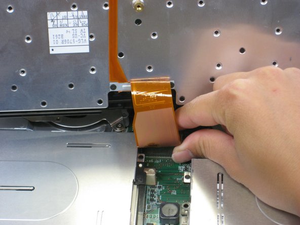
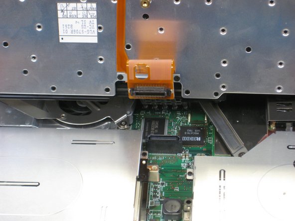
Locate the connector attached to the motherboard.
-
Disconnect the ribbon cable by removing the connector.
-
-
Este passo não foi traduzido. Ajude a traduzi-lo
-
Lift and remove the keyboard.
-
Remove the two 5.6mm screws.
-
Remove the 16.7mm screw.
-
-
Este passo não foi traduzido. Ajude a traduzi-lo
-
Remove the 5.6mm screw that holds the LCD to the upper case.
-
-
Este passo não foi traduzido. Ajude a traduzi-lo
-
Remove the 5.6mm screw on the left side of the three-pronged connector.
-
Remove the other two 16.7mm screws.
-
Lift and remove connector.
-
-
Este passo não foi traduzido. Ajude a traduzi-lo
-
Pull out the white tab connecting the LCD to the motherboard.
-
-
Este passo não foi traduzido. Ajude a traduzi-lo
-
Turn the laptop so that the back is facing you.
-
Remove the four 5.6mm long screws.
-
-
Este passo não foi traduzido. Ajude a traduzi-lo
-
Gently lift the LCD monitor up and out.
-
Remove the black plastic tab.
-


Cancelar: não concluí este guia.
Uma outra pessoa concluiu este guia.
Equipe

Cal Poly, Team 4-44, Amido Fall 2010 Membro de Cal Poly, Team 4-44, Amido Fall 2010
CPSU-AMIDO-F10S4G44
Membros da 4
Autoria de 26 guias