Esta versão pode conter edições incorretas. Mude para o último instantâneo verificado.
O que você precisa
-
Este passo não foi traduzido. Ajude a traduzi-lo
-
Remove to sticker on the back of the unit and then remove the two T5 scremws once this is done use a spudger to carefully pry off the silver cover.
-
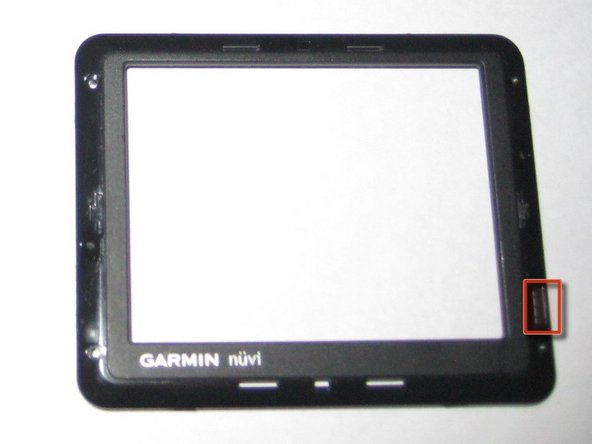
Once the tool is inserted it can slide around the entire device.
-
-
Este passo não foi traduzido. Ajude a traduzi-lo
-
Remove four small T5 torx screws.
-
Be gentle, the screws are easily stripped.
-
-
-
Este passo não foi traduzido. Ajude a traduzi-lo
-
Lift cover off of unit.
-
Be careful not to lose small rubber piece on the bottom right corner.
-
-
Este passo não foi traduzido. Ajude a traduzi-lo
-
Remove two T5 torx screws holding down logic board.
-
Disconnect battery.
-
-
Este passo não foi traduzido. Ajude a traduzi-lo
-
Gently lift the logic board out of the unit
-
Be careful not to damage the battery connector on the top of the unit.
-


Cancelar: não concluí este guia.
6 outras pessoas executaram este guia.
