Introdução
Replacing parts of the chassis, such as knobs and hex nuts, should be an easy task.
If your pedal is not functioning properly, it is possible to replace some parts by removing and re-soldering them to the motherboard.
However, we recommend that you review your warranty, and contact DigiTech directly if you are experiencing problems with the ISSI (Dynamic RAM) or Audio DNA chips.
O que você precisa
-
-
Push in the release pins with an Allen Wrench or the tip of an instrument cable to remove the pedal from the chassis.
 Pergunte ao FixBot
-
-
-
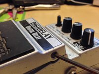
Remove knobs from the potentiometers by gripping firmly and pulling away from the chassis.
-
-
-
Turn the unit upside down, so that the top face of the pedal is facing away from you.
-
Use a 7/64 inch Allen Wrench to remove the 4 hex screws from the bottom of the chassis.
-
Remove the bottom of the chassis to reveal the back of the motherboard.
-
-
-
Use a Vice Grip or an Adjustable Crescent Wrench to remove the hex nuts and washers from the 3 line input/output jacks.
-
-
-
The motherboard can be easily removed from the chassis by lifting gently towards the potentiometers.
-
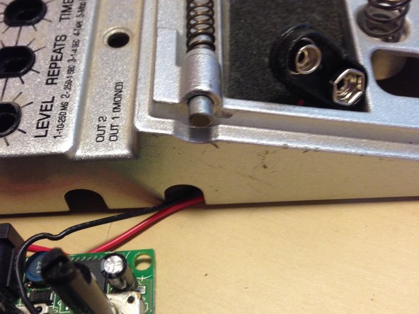
Remove only partially, ensuring not to tug too hard on the red and black wires connected to the 9V battery snap connector.
-
-
-
Remove the 9V battery snap connector from the battery casing before attempting to completely remove the motherboard from the chassis.
-
-
-
-
There are 4 potentiometers that stick out from the top of the motherboard toward the DC adapter port.
-
It is possible to replace these potentiometers by re-soldering their connection points on the back of the motherboard.
-
From the solder side: Heat the lugs one by one - With the soldered side facing up, as you heat each leg and it is molten - give the board a jolt and they will fall downward. Repeat one by one until they're all out.
-
-
-
Turn the motherboard over, and you will notice how 1 potentiometer furthest to your left has 6 soldering connection points. This is the potentiometer for the Mode Knob, which allows you to toggle between different types of delay.
-
The other 3, from left to right, are your Time, Repeat, and Level potentiometers. These all have 5 soldering connection points.
-
-
-
There are 2 output jacks located on left of the motherboard. The top jack is your 2nd line out, and the bottom is your 1st (mono) line out.
-
The single 1/4 jack on the right of the motherboard is your line input.
-
-
-
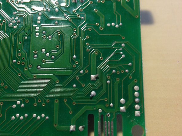
Turn the motherboard over, and you will notice how all three 1/4 inch jacks are secured by 3 soldering connection points each.
-
If you wish to replace any of these jacks, simply re-solder the connection to your replacement pieces at these points.
-
-
-
The red LED light, which signals whether your pedal is active or bypassing a signal, rises out of the central portion of the motherboard between the three 1/4 inch jacks.
-
The LED light is soldered at 2 small connection points at the back of the motherboard.
-
To replace this part, simply re-solder at the aforementioned connection points.
-
-
-
The DC Adapter Port is located at the top of the mother board in the center, just above the potentiometers.
-
-
-
The DC Adapter Port is soldered at 3 large connection points in the back of the motherboard.
-
To replace this part, simply re-solder at these connection points.
-
-
-
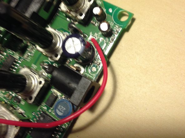
The 9V Battery Snap Connector is connected to motherboard via 2 wires: 1 red and 1 black.
-
The red wire is soldered to the left of the DC Adapter Port, and the black wire is soldered just below the single 1/4 inch line input jack.
-
To replace the 9V Battery Snap Connector, simply re-solder the connection in the back of the motherboard at these two points.
-
-
-
The Circuit Switch is a grey box with a circle on its top face, just left of the ISSI and Audio DNA chips.
-
The Circuit Switch is operated by a Pedal Switch Arm attached to the Pedal Cover.
-
This Switch is soldered at 2 small connection points in the back of the motherboard; re-solder at both connections to replace this part.
-
-
-
Delay pedals are generally built around a Dynamic RAM. This chip stores small amounts of info and instantly plays them back, creating the delay effect.
-
If your ISSI Chip is malfunctioning, we recommend that you review your warranty and contact DigiTech directly.
-
-
-
The Audio DNA is responsible for Digital Signal Processing (DSP), which drives the modeling and effect processing of the pedal.
-
If your Audio DNA Chip is malfunctioning, we recommend that you review your warranty and contact DigiTech directly.
-


To reassemble your device, follow these instructions in reverse order.
Cancelar: não concluí este guia.
6 outras pessoas executaram este guia.
3Comentários do guia
Anyone have a part number or source for a replacement circuit switch?
If you find it please let me know, also does anyone know what part of the motherboard is responsible for the tap tempo? I really appriciate this guide!
Mine on the main output (Mono) is not giving any effect, it turns on and off but only the DI signal without active effect, while on the next output (stereo) it works without problems. Both provide pre-guitar signal and previous effects, but the Digidelay effect only works on the stereo output. Have you ever seen anything like it?