Esta versão pode conter edições incorretas. Mude para o último instantâneo verificado.
O que você precisa
-
Este passo não foi traduzido. Ajude a traduzi-lo
-
Rotate the photo printer so that the bottom of the case faces upward.
-
-
Este passo não foi traduzido. Ajude a traduzi-lo
-
Use a Phillips #2 screwdriver to remove the three 5.65 mm screws on the bottom panel of the case in a counter-clockwise fashion.
-
-
Este passo não foi traduzido. Ajude a traduzi-lo
-
Rotate the device so that it is upright again. Under the LCD Panel there is a 9.62 mm screw, unscrew using a Phillips #2 screwdriver.
-
-
Este passo não foi traduzido. Ajude a traduzi-lo
-
Remove the back panel of the case by pulling directly back.
-
-
Este passo não foi traduzido. Ajude a traduzi-lo
-
Rotate the photo printer so that the bottom panel faces up once again. Now lift off the bottom panel of the case to access all internal components.
-
-
-
Este passo não foi traduzido. Ajude a traduzi-lo
-
Finally remove the side panel with the ink-cartridge door by holding the right side and pulling backwards with the left side.
-
-
Este passo não foi traduzido. Ajude a traduzi-lo
-
Carefully remove the inner components of the device by lifting the inner components up and out of the casing.
-
-
Este passo não foi traduzido. Ajude a traduzi-lo
-
Locate the red and black cable that is connecting the fan to the top of the logic board.
-
-
Este passo não foi traduzido. Ajude a traduzi-lo
-
Carefully, remove the red and black cable from the logic board by pulling gently in order to isolate the cooling fan from the device.
-
-
Este passo não foi traduzido. Ajude a traduzi-lo
-
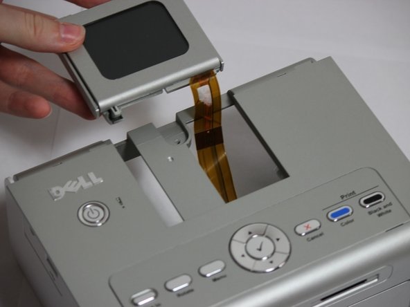
Locate the data ribbon that connects the LCD panel to the mother board.
-
Carefully unclip the ribbon from the mother board.
-
-
Este passo não foi traduzido. Ajude a traduzi-lo
-
Slide the LCD panel out and away from the printer case.
-
-
Este passo não foi traduzido. Ajude a traduzi-lo
-
Use a Phillips 00 screwdriver to remove the four 5.4 mm screws behind where the LCD screen is.
-


Equipe

Cal Poly, Team 14-7, Forte Spring 2012 Membro de Cal Poly, Team 14-7, Forte Spring 2012
CPSU-FORTE-S12S14G7
Membros da 4
Autoria de 12 guias