Esta versão pode conter edições incorretas. Mude para o último instantâneo verificado.
O que você precisa
-
Este passo não foi traduzido. Ajude a traduzi-lo
-
Lay the computer on its side; you will see a blue knob.
-
Turn this knob 90 deg clockwise.
-
-
Este passo não foi traduzido. Ajude a traduzi-lo
-
Slide the panel case forward about 1/2 inch while knob is turned.
-
Lift panel case off computer.
-
-
Este passo não foi traduzido. Ajude a traduzi-lo
-
Remove the large blue cover from the computer, there are no screws or tabs keeping it in place.
-
-
Este passo não foi traduzido. Ajude a traduzi-lo
-
Pull the heat sink out of the computer while pressing on the release tab.
-
-
Este passo não foi traduzido. Ajude a traduzi-lo
-
Remove the power supply that connects the upper fan to the motherboard. The power supply has black, red, green and yellow wires.
-
-
Este passo não foi traduzido. Ajude a traduzi-lo
-
Remove the rubber grommets from the base of the fan. A spudger may be useful.
-
-
Este passo não foi traduzido. Ajude a traduzi-lo
-
Press on the blue release tab and pull the upper fan out of the computer.
-
-
Este passo não foi traduzido. Ajude a traduzi-lo
-
Remove the power supply that connects the lower fan to the motherboard, distinguished by it's black, red, green and yellow wires.
-
-
Este passo não foi traduzido. Ajude a traduzi-lo
-
Remove the rubber grommets from the base of the fan. A spudger may be useful.
-
-
-
Este passo não foi traduzido. Ajude a traduzi-lo
-
The RAM are the two green cards in the corner of the computer.
-
At each end of the card, there are two white clips securing the RAM to the Motherboard.
-
-
Este passo não foi traduzido. Ajude a traduzi-lo
-
Push down both white clips with your thumbs until you hear a click.
-
The RAM cards can now be removed.
-
-
Este passo não foi traduzido. Ajude a traduzi-lo
-
Unplug the blue cable that connects the hard drive to the motherboard.
-
-
Este passo não foi traduzido. Ajude a traduzi-lo
-
Unplug the power supply, distinguished by its red and yellow wires.
-
-
Este passo não foi traduzido. Ajude a traduzi-lo
-
Squeeze the release tabs on either side of the hard drive.
-
Then slide the hard drive out of the computer while squeezing the tabs.
-
-
Este passo não foi traduzido. Ajude a traduzi-lo
-
Unplug the cable that connects the hard drive to the Motherboard.
-
-
Este passo não foi traduzido. Ajude a traduzi-lo
-
Press on the release tab and remove the motherboard speaker which is attached to the side of the tower.
-
-
Este passo não foi traduzido. Ajude a traduzi-lo
-
Unplug the power cable attached to the motherboard speaker.
-
-
Este passo não foi traduzido. Ajude a traduzi-lo
-
Remove four screws located at the back of the computer tower.
-
-
Este passo não foi traduzido. Ajude a traduzi-lo
-
Carefully detach the motherboard from the computer case.
-
-
Este passo não foi traduzido. Ajude a traduzi-lo
-
Lift the motherboard from the rest of the computer case.
-
-
Este passo não foi traduzido. Ajude a traduzi-lo
-
Unplug the cable that powers the hard drive, which has orange, red and yellow wires.
-
-
Este passo não foi traduzido. Ajude a traduzi-lo
-
Unplug the cable that powers the emergency shut off, distinguished by its red wires.
-
-
Este passo não foi traduzido. Ajude a traduzi-lo
-
Slide the Hard Drive Stand to left side.
-
Remove the stand from the rest of the rear panel.
-
-
Este passo não foi traduzido. Ajude a traduzi-lo
-
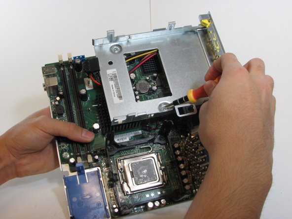
Remove the studs that support the Hard Drive Stand from the motherboard.
-
-
Este passo não foi traduzido. Ajude a traduzi-lo
-
Remove the four screws located on heat sink stand.
-
The heat sink stand can now be lifted from the motherboard.
-
-
Este passo não foi traduzido. Ajude a traduzi-lo
-
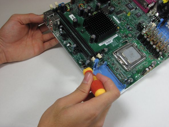
Remove the four screws holding the motherboard to the rear computer panel.
-
-
Este passo não foi traduzido. Ajude a traduzi-lo
-
The motherboard can now be removed from the remaining panel.
-


Cancelar: não concluí este guia.
11 outras pessoas executaram este guia.
Equipe

Cal Poly, Team 22-4, Maness Fall 2010 Membro de Cal Poly, Team 22-4, Maness Fall 2010
CPSU-MANESS-F10S22G4
Membros da 4
Autoria de 26 guias
2 comentários
Good job. Thanks for sharing, friend.
Great guide! I got stuck at the Mobo tray, I knew the black screws were involved but couldn't get it with out help. Thanks!
Fans can be removed with board tray, otherwise they're getting pulled off their rubber isolating feet. Once out with the mobo, the fans slide off the board tray with their plastic shoes attached.