Esta versão pode conter edições incorretas. Mude para o último instantâneo verificado.
O que você precisa
-
Este passo não foi traduzido. Ajude a traduzi-lo
-
Unplug the coffee-maker from the power source.
-
Use a Phillips head screwdriver to remove the four 7mm screws from the back and the three 8mm screws from the bottom. This will release the bottom cover.
-
-
Este passo não foi traduzido. Ajude a traduzi-lo
-
Use tweezers to remove the two rubber feet marked within the provided pictures.
-
Remove both 8mm Phillips head screws found within the holes where the feet were just removed.
-
-
Este passo não foi traduzido. Ajude a traduzi-lo
-
Carefully pull the cover off the bottom of the coffee maker. This will give you access to the inside of the coffee maker.
-
Pull the gray ribbon cable strait out of the black containment box.
-
-
-
Este passo não foi traduzido. Ajude a traduzi-lo
-
Locate the Phillips head screws holding the highlighted plastic shield in place.
-
Remove the two 14mm screws with a Phillips head screwdriver.
-
Carefully slide the shield out of place along the power cord and set it aside.
-
-
Este passo não foi traduzido. Ajude a traduzi-lo
-
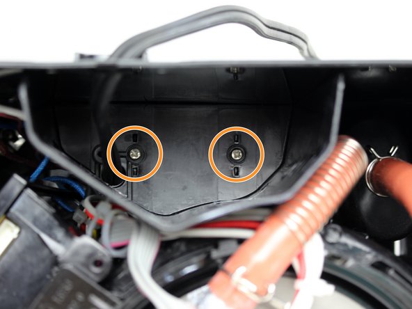
Remove the two 14mm Phillips head screws securing the plastic containment box.
-
Pull the plastic containment box straight out of the coffee maker.
-
-
Este passo não foi traduzido. Ajude a traduzi-lo
-
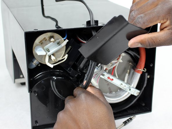
Remove the four 11mm Phillips head screws in each corner of the plastic containment box.
-
Pull the top from the plastic housing.
-
-
Este passo não foi traduzido. Ajude a traduzi-lo
-
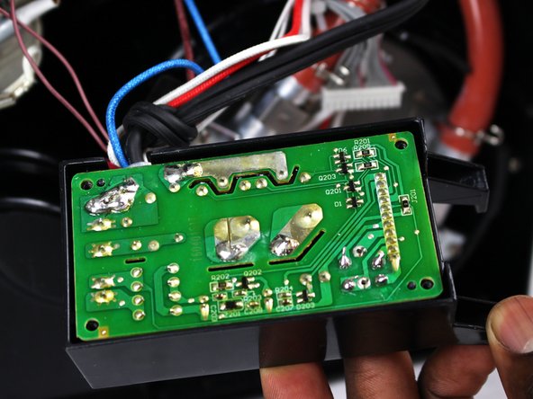
Pull the circuit board out of the containment box.
-
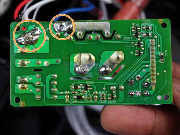
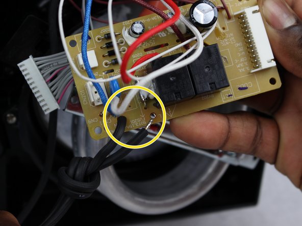
Locate the power cable connection point on the circuit board.
-
Desolder the power cable wires connected to the board.
-
Replace the power cable with the corresponding wires of the new power cable.
-


Cancelar: não concluí este guia.
2 outras pessoas executaram este guia.
Equipe

Sam Houston State, Team S17-G2, Blackburne Spring 2018 Membro de Sam Houston State, Team S17-G2, Blackburne Spring 2018
SHSU-BLACKBURNE-S18S17G2
Membros da 3
Autoria de 4 guias