Esta versão pode conter edições incorretas. Mude para o último instantâneo verificado.
O que você precisa
-
Este passo não foi traduzido. Ajude a traduzi-lo
-
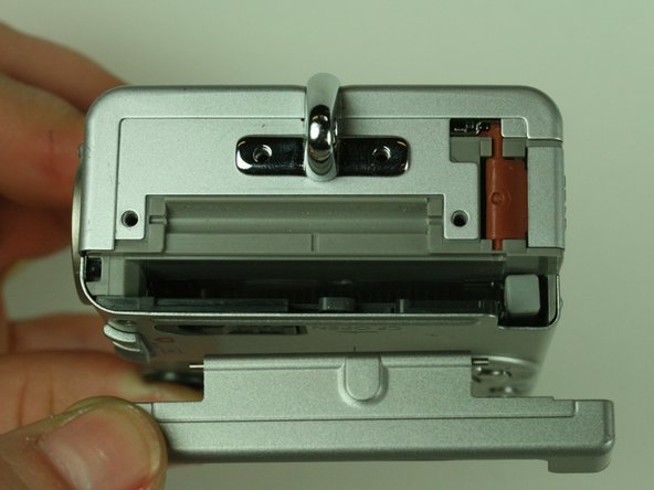
On the backside of the camera, remove the 4.75 mm screw that sits at the top right corner.
-
Remove the four 4.75 mm screws that sit at the bottom of the camera.
-
-
Este passo não foi traduzido. Ajude a traduzi-lo
-
On the side of the camera, remove the two 4.75 mm screws that sit near the USB digital terminal.
-
-
Este passo não foi traduzido. Ajude a traduzi-lo
-
On the side of the camera, remove the four 4.75 mm screws that sit near the wrist strap mount.
-
Remove the two small metal plates, which the four screws hold in place.
-
-
Este passo não foi traduzido. Ajude a traduzi-lo
-
Remove the small black plastic piece and set it aside. If necessary, use tweezers to remove the small black plastic piece.
-
Detach the front case and back case.
-
-
Este passo não foi traduzido. Ajude a traduzi-lo
-
Remove the 3.5 mm screw that sits on the metal plate at the bottom of the camera.
-
Remove the two other 3.5 mm screws that sit on the side, to the left of the screw you just removed.
-
-
-
Este passo não foi traduzido. Ajude a traduzi-lo
-
A ribbon cable attaches to the metal plate and to the main circuit board, on the front of the camera.
-
Gently release the black latch.
-
Remove the ribbon cable and metal plate assembly.
-
-
Este passo não foi traduzido. Ajude a traduzi-lo
-
On the backside of the camera, remove the 3.5 mm screw that sits to the left of the viewfinder and above the LCD screen.
-
Remove the second 3.5 mm screw that sits directly above the LCD screen.
-
Gently detach the ribbon cable.
-
-
Este passo não foi traduzido. Ajude a traduzi-lo
-
Locate the ribbon cable on the main circuit board, which sits below the lens.
-
Gently release the black latch on the ribbon cable connector and detach the ribbon cable.
-
-
Este passo não foi traduzido. Ajude a traduzi-lo
-
On the main circuit board, gently release the black latches of the four ribbon cables.
-
Gently detach the ribbon cables.
-
-
Este passo não foi traduzido. Ajude a traduzi-lo
-
Detach the white-capped and green-capped wires, which sit near the flash.
-
-
Este passo não foi traduzido. Ajude a traduzi-lo
-
Using a spudger, gently detach the shutter button assembly from the camera.
-
-
Este passo não foi traduzido. Ajude a traduzi-lo
-
Remove the four 3.5 mm screws that hold the main circuit board.
-
-
Este passo não foi traduzido. Ajude a traduzi-lo
-
In a hinge-like motion, gently lift the bottom of the main circuit board, which is the side without the soldering points.
-
Gently detach the white ribbon cable from the underside of the main circuit board.
-
-
Este passo não foi traduzido. Ajude a traduzi-lo
-
Gently desolder the two ribbon cables attached to the motherboard.
-
Remove the motherboard.
-


Cancelar: não concluí este guia.
2 outras pessoas executaram este guia.
Equipe

Cal Poly, Team 5-19, Amido Winter 2011 Membro de Cal Poly, Team 5-19, Amido Winter 2011
CPSU-AMIDO-W11S5G19
Membros da 4
Autoria de 6 guias