Introdução
Please follow these steps to replace the LCD Screen. Your LCD screen may require replacement if it no longer displays an image or has been cracked or damaged.
O que você precisa
-
-
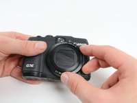
Open the battery flap on the bottom of the camera by applying pressure and pushing in the direction of the arrow.
-
Remove your finger and allow the flap to pop open.
-
-
-
Push the brown lever so that it pivots counterclockwise.
-
Grip and remove the battery.
-
-
-
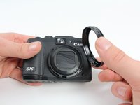
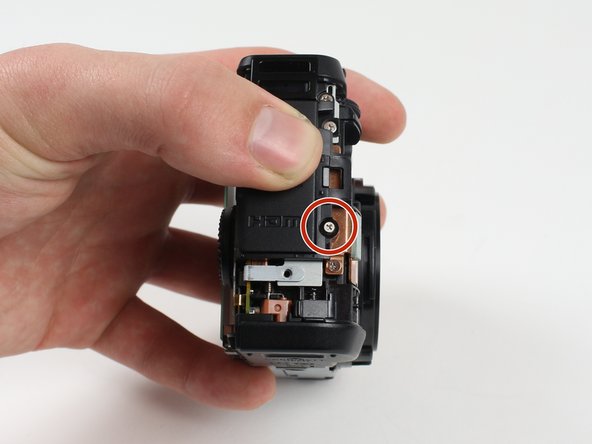
Remove the ring around the lens by simultaneously pressing the black button located at the bottom right of the ring and rotating the ring counterclockwise.
-
-
-
Ferramenta utilizada neste passo:Tweezers$4.99
-
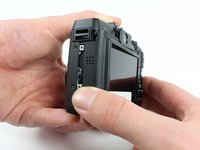
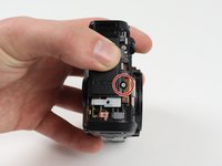
Reorient the camera so that you are looking at the back.
-
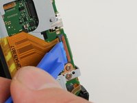
Unplug the button circuit board from the motherboard by unlocking the ZIF connector (gently lift the brown lock that keeps the cable in place).
-
Pull the connector downwards with the tweezers.
This is not completely correct. In order to pull the connector down without force, the little grey tap on the top of the connectorbox has to be flipped up.
This particular step cost me the connection to the button curcuit board. I would be grateful for an indication of where I can buy a replacement. Thanks.
You saved my connection. Thank you. iFixit... I'm somewhat disappointed these steps haven't been corrected.
It's worth noting that I had no luck with tweezers when attempting to remove the ribbon cable. The correct procedure would be to carefully lift the plastic clip with an iFixit spudger and then continue to step 12. The ribbon cable will pull out gently without any other coercion.
The clip is a red/terracotta colour, this should be lifted like a lid (the hinge is mounted in the grey housing). The connector should be pulled downward as described. This should definitely be corrected. Thanks for the comments to assist. I added this for extra clarity on the colours only.
-
-
-
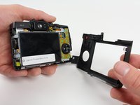
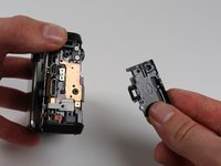
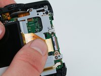
Unlock the ZIF connector for the large connector ribbon by lifting up on the brown flap with the plastic opening tool.
-
Gently pull the connector straight out of the housing with your fingers.
-
-
-
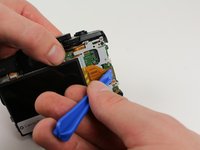
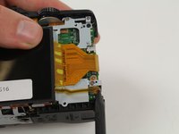
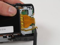
Unplug the small connector ribbon by pulling the cable outwards from the camera using a spudger or your fingers.
Be careful with this step. I broke the black connector off the motherboard for the small ribbon cable. It is very fragile. You might want to push down on the black connector to hold it in place while gently pulling the ribbon to the right to extract it from the connector. Don’t let the black connect pull up or twist.
-


To reassemble your device, follow these instructions in reverse order.
To reassemble your device, follow these instructions in reverse order.
Cancelar: não concluí este guia.
8 outras pessoas executaram este guia.

Equipe

Cal Poly, Team 70-6, Forte Winter 2016 Membro de Cal Poly, Team 70-6, Forte Winter 2016
CPSU-FORTE-W16S70G6
4 Membros
Autoria de 7 guias
8 comentários
1) Step 11 needs to be updated
2) Add Tweezers to the "tools needed" part at the beginning
Otherwise nice instruction
Nice set of instructions, although I had a real problem at step 11, and I recommend it be updated.
The instructions for step 14 should be copied-and-pasted into step 11.
Looking at the instructions for step 11, it was not at all clear that the brown lock-flap needed to be lifted first, and that the connector would then come out quite easily. Applying tweezers to the connector without first knowing about the brown lock-flap could easily lead to damaging the ribbon cable, as almost happened in my case.
So, for anyone reading this (in case the instruction set is not updated by the author), use the instructions for step 14 when you are at step 11. The connector will come out easily after the brown lock-flap is lifted, and the "connector" is NOT the grey plastic part that you see; it is in fact simply the end of the ribbon cable.
Thank You to the author. This instruction set saved me a bunch of money.
Also about step 11: Twezers may harm the cable. After opening the brown lock you can just carefully let the cable get out on step 13 while lifting the button circuit board away from the camera. On the reverse order,after replacement, twezers are needed to push the cable gently in.
Great instructions and comments, a real help however any ideas where I can get a good quality LCD please?
Just amazed myself by carefully following the instructions and changing out the screen. The onIy real concern it that I pushed the large ribbon in far enough so it locked in when I locked the connector back down. I didn’t want to force it too much, and just hope I got it inserted all the way. Dave T
Thank you! Great instructions and comments, and I get to use my favorite camera for another day!
The instructions are also valid for the Canon G15. which has one less 3.3mm screw at the bottom. notices that the 3.3mm screws also come into 3 lengths in the G15.
I found that taking out the flex cables from the ZIF sockets much easier that inserting the new ones in the same sockets. Especially the small flex cable in step 15. Also the procedure to put back the covers would be easier if you put back the rear cover (without the screws) first before the front cover.
Grear instructions overall.