Esta versão pode conter edições incorretas. Mude para o último instantâneo verificado.
O que você precisa
-
Este passo não foi traduzido. Ajude a traduzi-lo
-
Hold the phone with the back facing you.
-
Press the silver tab down and remove the cover.
-
-
Este passo não foi traduzido. Ajude a traduzi-lo
-
Pull up on the top edge of the battery to remove it.
-
-
Este passo não foi traduzido. Ajude a traduzi-lo
-
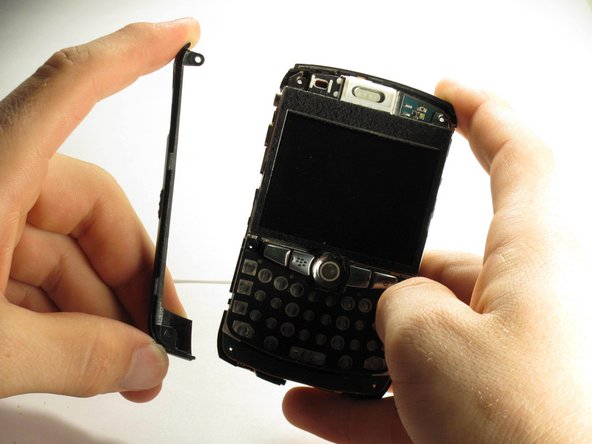
Use a plastic opening tool to gently pry the bottom cover loose.
-
Pull the cover from the front of the phone after the back is loose.
-
-
Este passo não foi traduzido. Ajude a traduzi-lo
-
Remove the two top screws with a T5 Torx screwdriver.
-
-
-
Este passo não foi traduzido. Ajude a traduzi-lo
-
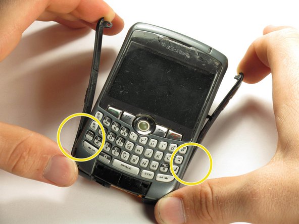
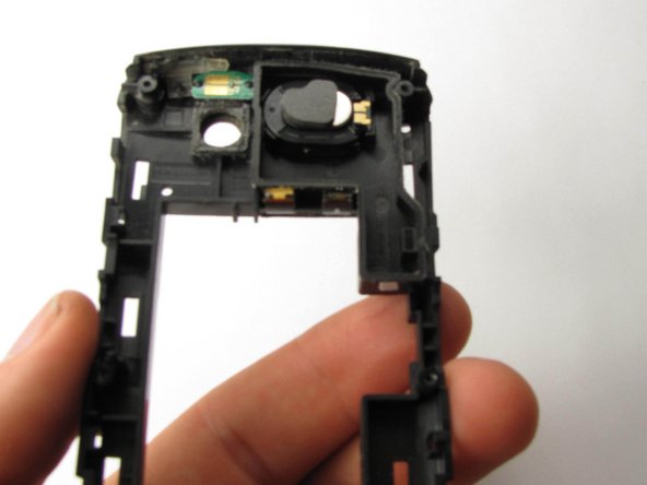
Gently pry off the side casings from the top.
-
You will not need to remove the sides on the bottom.
-
-
Este passo não foi traduzido. Ajude a traduzi-lo
-
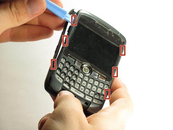
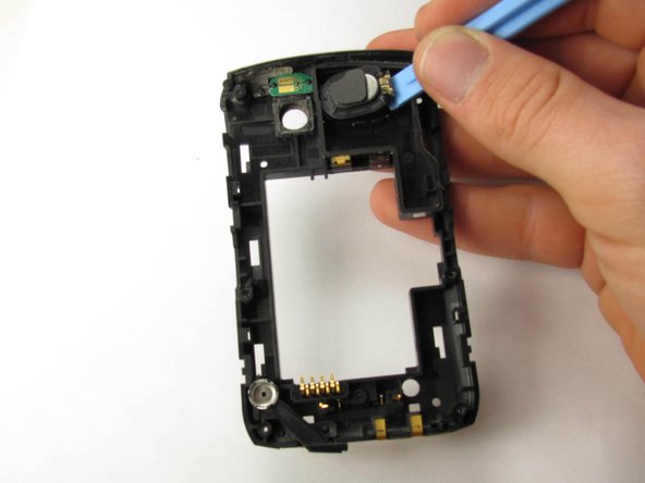
Use a plastic opening tool to detach the securing clips holding the the front panel in place.
-
-
Este passo não foi traduzido. Ajude a traduzi-lo
-
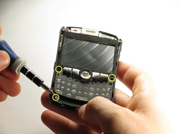
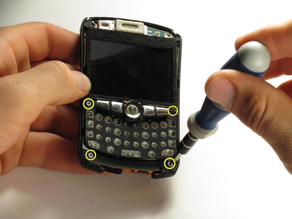
Use a T6 Torx screwdriver to remove the four screws located on the corners of the keyboard frame.
-
-
Este passo não foi traduzido. Ajude a traduzi-lo
-
After the bottom two screws have been removed the side casings can be removed.
-


Cancelar: não concluí este guia.
Uma outra pessoa concluiu este guia.
Equipe

Cal Poly, Team 3-6, Regan Fall 2011 Membro de Cal Poly, Team 3-6, Regan Fall 2011
CPSU-REGAN-F11S3G6
Membros da 5
Autoria de 9 guias