Esta versão pode conter edições incorretas. Mude para o último instantâneo verificado.
O que você precisa
-
Este passo não foi traduzido. Ajude a traduzi-lo
-
Place the computer upside down.
-
Using your thumbs, slide both latches away from each other (towards the outside).
-
Push the battery out with your fingers.
-
-
Este passo não foi traduzido. Ajude a traduzi-lo
-
Using a Phillips #0 screwdriver, remove the two screws from the case.
-
-
Este passo não foi traduzido. Ajude a traduzi-lo
-
Locate the four tabs above the F1, F10, INSERT, and between the F5 and F6 keys.
-
Starting with the tab above the F1 key, press the tabs inward using your fingernail or spudger. Continue this process for the rest of the tabs.
-
-
Este passo não foi traduzido. Ajude a traduzi-lo
-
Pull the keyboard up from the top at a 45 degree angle. Place it upside down on the touchpad.
-
Pull the wide ribbon cable laterally from its socket on the motherboard to free the keyboard.
-
-
Este passo não foi traduzido. Ajude a traduzi-lo
-
Using a Phillips #0 screwdriver, remove the screws at the bottom of the chassis to remove the top panel.
-
-
Este passo não foi traduzido. Ajude a traduzi-lo
-
Remove the six screws from below the keyboard with a Phillips #0 screwdriver.
-
-
Este passo não foi traduzido. Ajude a traduzi-lo
-
Use your fingernails or a pry tool to gently separate both halves of the case. Begin at the front and work around the entire case.
-
-
-
Este passo não foi traduzido. Ajude a traduzi-lo
-
Remove the internal cables from front to back.
-
Use your fingers to gently remove the cables from their sockets.
-
-
Este passo não foi traduzido. Ajude a traduzi-lo
-
After separating the top and bottom halves of the case, lay them flat on the work area.
-
-
Este passo não foi traduzido. Ajude a traduzi-lo
-
Remove the six screws (three on each side) holding the top panel of the chassis to the display with a Phillips #0 screwdriver.
-
-
Este passo não foi traduzido. Ajude a traduzi-lo
-
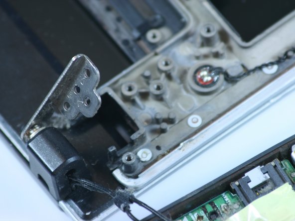
Remove the display by leaving the display flat on the table and tilting the panel up (as if opening the laptop). This will shift the hinges to allow easy removal.
-
Separate the chassis from the display. If the screws were removed properly, it should come free.
-
-
Este passo não foi traduzido. Ajude a traduzi-lo
-
Remove seven screws from the bezel with a Phillips #0 screwdriver.
-
-
Este passo não foi traduzido. Ajude a traduzi-lo
-
Using a fingernail or opening tool, gently pry the bezel up from the screen.
-
-
Este passo não foi traduzido. Ajude a traduzi-lo
-
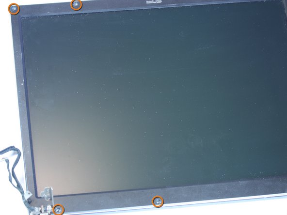
Remove six screws from underneath the bezel with a Phillips #0 screwdriver. Two are located next to each hinge and one at each top corner.
-
-
Este passo não foi traduzido. Ajude a traduzi-lo
-
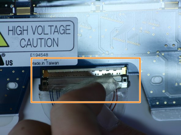
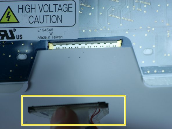
Look behind the display. Locate the display connector.
-
Peel back the tape from over the connector.
-
Remove the connector from the display and slowly pull the cable away, peeling the tape back along the way.
-
-
Este passo não foi traduzido. Ajude a traduzi-lo
-
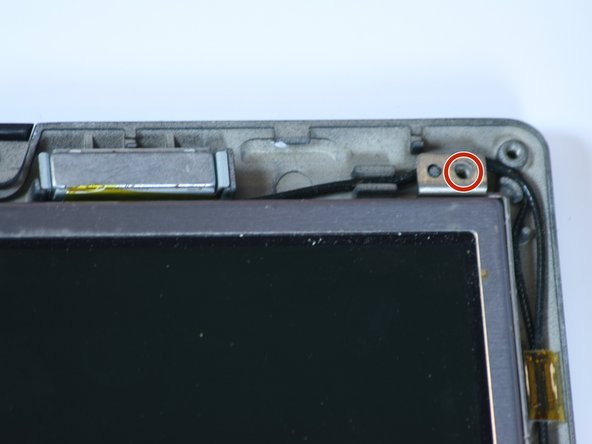
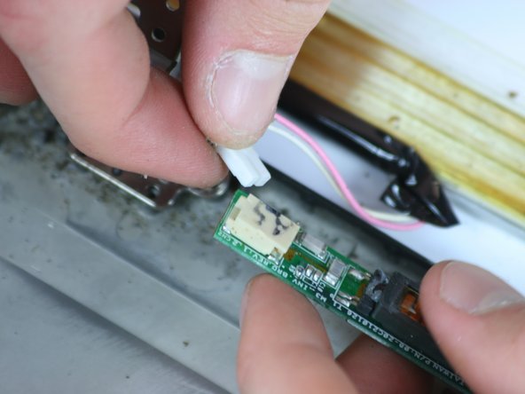
Remove the small connector located near the right hinge.
-
-
Este passo não foi traduzido. Ajude a traduzi-lo
-
The display is now completely removed and can be replaced.
-


Cancelar: não concluí este guia.
Uma outra pessoa concluiu este guia.
Equipe

Cal Poly, Team 2-9, Johann Summer 2010 Membro de Cal Poly, Team 2-9, Johann Summer 2010
CPSU-JOHANN-R10S2G9
Membros da 5
Autoria de 10 guias