Introdução
These steps are very similar to steps for LED replacement. The only difference between these two guides are the solder points. Pay close attention to the pictures to make sure that you will be removing the solder from the correct points.
O que você precisa
-
-
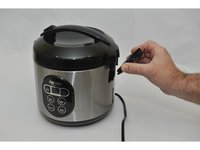
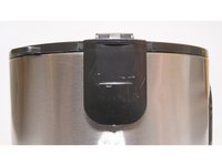
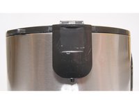
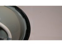
The first step is removing the condensation catcher in order to reach the control panel. We do this by pinching the condensation catcher as shown, on both sides and pull the condensation catcher away from the cooker.
 Pergunte ao FixBot
-
-
-
Once the condensation catcher has been removed, set it aside for reassembly later.
-
Now make sure you have a a Phillips head screwdriver, size PH2. This tool will allow you to remove the screw that was behind the condensation catcher.
-
-
-
Gently remove the piece that was held in place by the screw, you do this by pulling out from the top, then pulling up. This will expose the hinges for the lid.
-
-
-
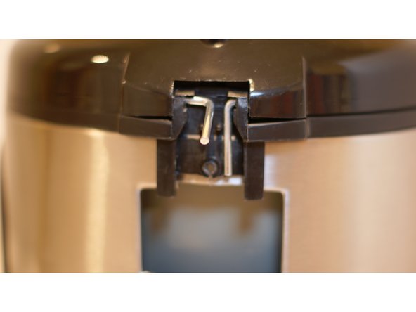
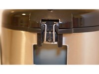
To remove the hinge, gently rotate the bottom of the rod upwards, then push inward to pull the rod out. Repeat the process for each rod. This will allow the lid to be removed.
-
-
-
-
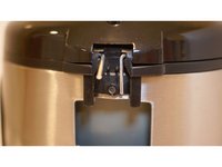
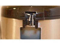
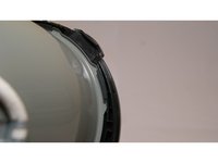
Locate the piece on the black plastic trim that is opposite from where the hinges were. Carefully, pry the bottom edge of this piece outward (away from the stainless steel side) about 1/4 inch to pull the tab out of it's hole. Once the bottom is pried out a bit, the tab can be seen from the bottom. Press up on the tab with a screwdriver.
-
-
-
Next, you must remove the upper black trim which is connected to the inside liner with tabs. To do this you must hold the interior walls still, while rotating the trim so that the tabs line up with the slots. (tabs cannot be seen at this point, pics are to give you an idea of what you cannot see inside the device)
-
-
-
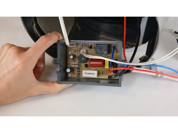
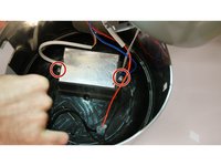
Using a Phillips head screwdriver, size PH2, remove screws from the control module to expose wired connections.
-
-
-
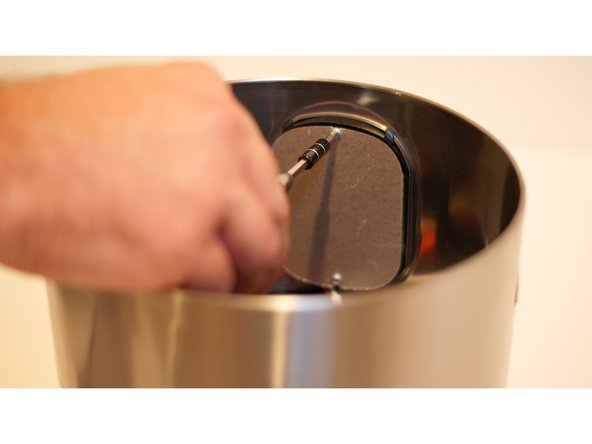
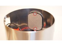
Remove the two screws holding the cardboard cover over the Interface using a Phillips head screwdriver, size PH2.
-
-
-
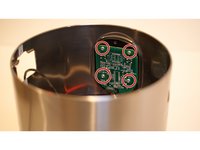
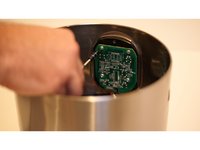
Using a Phillips head screwdriver, size PH2, remove the four screws holding the interface in place.
-
-
-
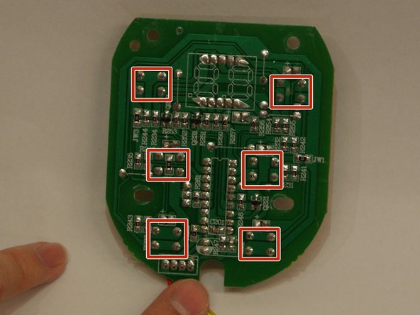
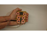
These pictures identify the Push Buttons along with their corresponding solder points through the back of the circuit board.
-
-
-
Heat each point with the soldering iron while pulling the Push Button out from the front in order to remove the buttons.
-


To reassemble your device, follow these instructions in reverse order.
Equipe

USF Tampa, Team 2-3, Sullivan Fall 2015 Membro de USF Tampa, Team 2-3, Sullivan Fall 2015
USFT-SULLIVAN-F15S2G3
3 Membros
Autoria de 8 guias