Esta versão pode conter edições incorretas. Mude para o último instantâneo verificado.
O que você precisa
-
Este passo não foi traduzido. Ajude a traduzi-lo
-
Lay the display facing down with the stand away from you.
-
Remove the three size 2.0 hex screws on the swing arm and remove the swing arm as well as the plastic shield under it.
-
-
Este passo não foi traduzido. Ajude a traduzi-lo
-
Remove the size 2.5 hex screws from each corner that connects the panels to the display and remove them.
-
-
Este passo não foi traduzido. Ajude a traduzi-lo
-
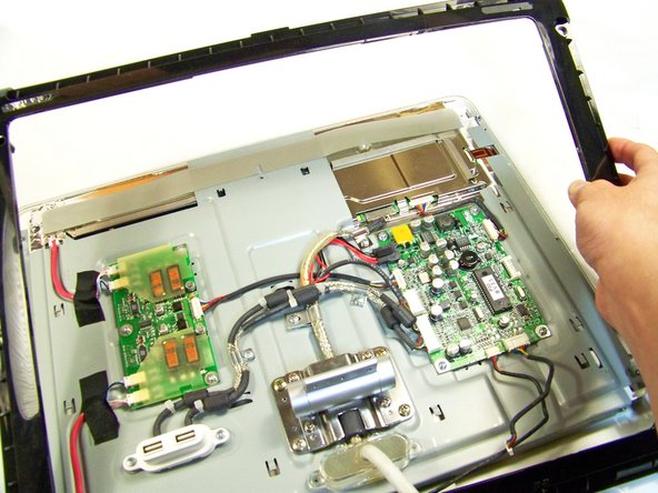
Rotate the display so the legs of the display are now facing you
-
Grip the top of the clear panel and lift it upwards, and pull the ADC cable through the hole.
-
-
Este passo não foi traduzido. Ajude a traduzi-lo
-
Remove the grey back panel by lifting the bottom and pulling the ADC cable through the hole.
-
-
Este passo não foi traduzido. Ajude a traduzi-lo
-
The next layer will be a shiny metal panel, which might have some stickers. Make sure to remove these stickers.
-
-
-
Este passo não foi traduzido. Ajude a traduzi-lo
-
Now locate and remove the lone Phillips screw holding the EMI shield to the display
-
-
Este passo não foi traduzido. Ajude a traduzi-lo
-
Now that the screw has been removed, slide the panel towards your body and lift it out.
-
-
Este passo não foi traduzido. Ajude a traduzi-lo
-
Using the spudger, remove the four black panel covers on the edges of the display.
-
-
Este passo não foi traduzido. Ajude a traduzi-lo
-
Remove the two connections that connect the buttons to the logic board
-
-
Este passo não foi traduzido. Ajude a traduzi-lo
-
Remove the outer frame and and pull the cables through the hole. Flip the frame upside down.
-
-
Este passo não foi traduzido. Ajude a traduzi-lo
-
The red highlighted box is the power button
-
The teal highlighted box is the brightness button
-
-
Este passo não foi traduzido. Ajude a traduzi-lo
-
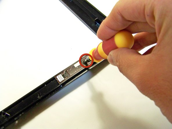
Remove the screws at the bottom holding the button(s) down
-


Cancelar: não concluí este guia.
Uma outra pessoa concluiu este guia.
Equipe

Cal Poly, Team 3-20, Maness Winter 2010 Membro de Cal Poly, Team 3-20, Maness Winter 2010
CPSU-MANESS-W10S3G20
Membros da 4
Autoria de 15 guias