Esta versão pode conter edições incorretas. Mude para o último instantâneo verificado.
O que você precisa
-
Este passo não foi traduzido. Ajude a traduzi-lo
-
Pull the keyboard tabs toward you while lifting up on the keyboard until it releases from it's hold.
-
To lift the keyboard out pull it up and away from you. Then place the keyboard on the track pad.
-
-
Este passo não foi traduzido. Ajude a traduzi-lo
-
Pull the keyboard ribbon vertically from the logic board to release connection.
-
-
Este passo não foi traduzido. Ajude a traduzi-lo
-
Remove the two silver Phillips #1 screws that attach the heat shield to the metal framework.
-
Lift the heat shield up and toward you.
-
-
Este passo não foi traduzido. Ajude a traduzi-lo
-
Pull the PRAM battery cable vertically upward to disconnect it.
-
Remove the battery by pulling up and to the left.
-
-
Este passo não foi traduzido. Ajude a traduzi-lo
-
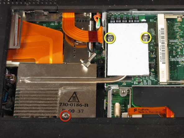
Remove the two T8 Torx screws that attach the heat sink to the processor.
-
Remove the long silver Phillips #1 screw from the heat sink.
-
-
Este passo não foi traduzido. Ajude a traduzi-lo
-
Lift up the heat sink unit from the left side and remove.
-
-
Este passo não foi traduzido. Ajude a traduzi-lo
-
Lift the processor on the right side and pull directly up.
-
The RAM chips should be in the slots on the processor.
-
-
Este passo não foi traduzido. Ajude a traduzi-lo
-
After removing the RAM, your laptop should now look like this.
-
-
-
Este passo não foi traduzido. Ajude a traduzi-lo
-
Locate the orange tab, which should be just left of the hard-drive.
-
You must disconnect this orange tab from the logic board to enable the next step.
-
It is better to do this by grabbing the plastic connection point, not the relatively flexible cable.
-
-
Este passo não foi traduzido. Ajude a traduzi-lo
-
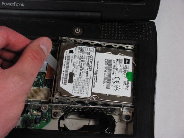
Grab the plastic strip shown here and gently remove, pulling up and left.
-
Pull left to avoid the hard drive catching the casing.
-
-
Este passo não foi traduzido. Ajude a traduzi-lo
-
Once you have removed the hard-drive, your laptop should like this.
-
-
Este passo não foi traduzido. Ajude a traduzi-lo
-
Remove the single black Torx screw from the modem.
-
Remove the black rectangle that is being held on by the one Torx screw.
-
-
Este passo não foi traduzido. Ajude a traduzi-lo
-
Using your fingers, lift the modem from the socket it is plugged into.
-
-
Este passo não foi traduzido. Ajude a traduzi-lo
-
Disconnect the cable that is attached to the end of the modem to remove the modem.
-
-
Este passo não foi traduzido. Ajude a traduzi-lo
-
Push the display back.
-
Put your index finger under the power button and gently pull the clutch cover back.
-
Repeat for the left side.
-
-
Este passo não foi traduzido. Ajude a traduzi-lo
-
Lift the clutch cover up and off. Pull it towards yourself.
-
-
Este passo não foi traduzido. Ajude a traduzi-lo
-
Remove the Torx screw that holds the display cable.
-
Pull out thick display inverter board by pulling it up and out. Two tabs will be holding it in place, you need to get pass these to pull the board free.
-
-
Este passo não foi traduzido. Ajude a traduzi-lo
-
Disconnect the white inverter cable. Pull it towards the left.
-
-
Este passo não foi traduzido. Ajude a traduzi-lo
-
Disconnect the inverter plug by pulling it up from the logib board.
-
-
Este passo não foi traduzido. Ajude a traduzi-lo
-
Turn the laptop around.
-
Open the port door.
-
Remove the four Torx screws.
-
-
Este passo não foi traduzido. Ajude a traduzi-lo
-
Turn the laptop so the front faces you.
-
Pull the black Airport antenna up.
-
-
Este passo não foi traduzido. Ajude a traduzi-lo
-
Pull the display up as you hold it firmly with both hands.
-


Equipe

Cal Poly, Team 4-2, Regan Spring 2011 Membro de Cal Poly, Team 4-2, Regan Spring 2011
CPSU-REGAN-S11S4G2
Membros da 4
Autoria de 6 guias