Esta versão pode conter edições incorretas. Mude para o último instantâneo verificado.
O que você precisa
-
Este passo não foi traduzido. Ajude a traduzi-lo
-
Move the battery catch to the "unlocked" position.
-
Pull back the second spring-loaded battery catch until the battery pops up.
-
Remove the battery.
-
-
Este passo não foi traduzido. Ajude a traduzi-lo
-
Turn the notebook around to face you.
-
There are two Phillips #00 screws securing the cover panel to the rest of the notebook. Remove these screws.
-
-
Este passo não foi traduzido. Ajude a traduzi-lo
-
Use a spudger to release the panel from the plastic retaining clips keeping it in place.
-
Remove the panel and set it aside.
-
-
Este passo não foi traduzido. Ajude a traduzi-lo
-
Unscrew the Phillips #00 screw which retains the hard drive in place.
-
Gently slide the hard drive to the left in order to disengage the SATA connectors.
-
Lift the drive out of the notebook.
-
-
Este passo não foi traduzido. Ajude a traduzi-lo
-
The RAM is protected by a transparent cellophane cover.
-
Lift this cover away from the RAM. It will not come free from the RAM.
-
-
Este passo não foi traduzido. Ajude a traduzi-lo
-
Pull back the retaining clips either side of the RAM.
-
It will spring up, ready to be removed.
-
-
Este passo não foi traduzido. Ajude a traduzi-lo
-
Hold on to opposite edges of the RAM chip and gently pull it diagonally upwards to remove it from the computer.
-
Repeat steps 5 and 6 for the second RAM chip if necessary.
-
-
Este passo não foi traduzido. Ajude a traduzi-lo
-
When reinserting RAM, push it diagonally downwards until almost all of the gold connector strip is inside the socket.
-
Push gently down on the RAM until the retaining clips click back over it.
-
-
-
Este passo não foi traduzido. Ajude a traduzi-lo
-
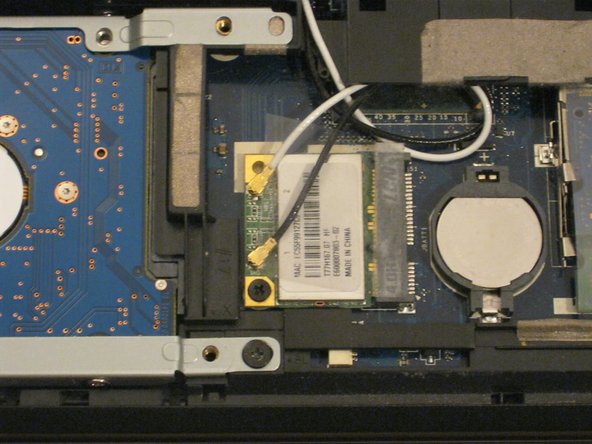
The WLAN card is protected by a transparent cellophane cover.
-
Lift this cover away from the WLAN card. It will not come free from the WLAN card socket.
-
-
Este passo não foi traduzido. Ajude a traduzi-lo
-
Use the pointy end of a spudger to remove the antenna connectors from the WLAN card.
-
-
Este passo não foi traduzido. Ajude a traduzi-lo
-
There is one Phillips #00 screw keeping the WLAN card attached to the notebook.
-
Remove this screw.
-
The WLAN card will spring up from the notebook at an angle.
-
-
Este passo não foi traduzido. Ajude a traduzi-lo
-
Just like RAM, hold the WLAN card by the edges and pull it out at an angle.
-
-
Este passo não foi traduzido. Ajude a traduzi-lo
-
You might also want to put the antenna cables back in using the flat end of a spudger.
-
-
Este passo não foi traduzido. Ajude a traduzi-lo
-
Unfold the laptop so that you are looking at the keyboard.
-
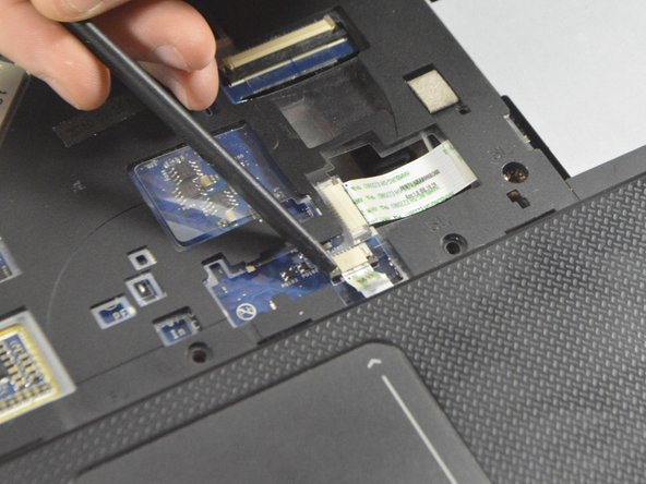
At the top right of the keyboard you will notice two clips above the 'Del' and 'End' keys.
-
Using your spudger, press these clips in to unlock the keyboard from the laptop
-
Slide the spudger along the top of the keyboard until the keyboard is able to easily be lifted up out of the laptop
-
-
Este passo não foi traduzido. Ajude a traduzi-lo
-
To detach this cable you must use the pointed edge of the spudger to press down on the locking mechanisms on each side.
-
After unlocking both sides of the ZIF connector remove the keyboard for replacement.
-
-
Este passo não foi traduzido. Ajude a traduzi-lo
-
Remove the 10 Phillips #0 screws on the bottom cover.
-
Remove the 4 Phillips #00 screws from under the battery.
-
-
Este passo não foi traduzido. Ajude a traduzi-lo
-
Remove the 8 Phillips #0 screws from under the keyboard.
-
-
Este passo não foi traduzido. Ajude a traduzi-lo
-
Release the two ribbon cables from the ZIF connectors in the same fashion as in Step 11 with the black spudger.
-
Once the mechanism is released you may remove the cable by hand.
-
The plastic cover can now be easily lifted and removed from the rest of the laptop.
-
-
Este passo não foi traduzido. Ajude a traduzi-lo
-
Remove the two remaining ribbon cables as described in Step 11.
-
-
Este passo não foi traduzido. Ajude a traduzi-lo
-
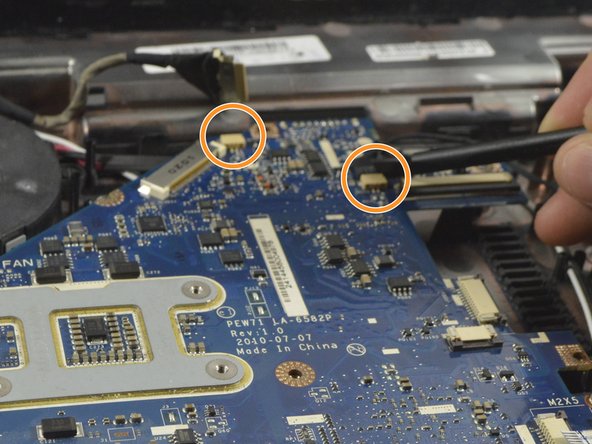
Remove the display cable with the spudger by pushing each end of the cable out of the connector until it is loose enough to be pulled out by hand.
-
In a similar fashion as with the display cable use the spudger to remove the two power cables from the motherboard.
-
-
Este passo não foi traduzido. Ajude a traduzi-lo
-
Remove the 3 Phillips #0 screws from the fan bracket.
-
Lift the fan up and place it back down above the heatsink.
-
The motherboard can be lifted from the side and and then to the right to free the I/O port from the enclosure. Some force may be required to release the heatsink.
-
-
Este passo não foi traduzido. Ajude a traduzi-lo
-
Rotate the motherboard to the right and lay it down so that the copper heatsink is facing up and parallel with the bottom of the monitor.
-
In this position the last cable to the motherboard can be disconnected using the spudger to push each end out until loose enough to pull the cable completely out.
-
The motherboard can now be completely removed from the laptop enclosure.
-
-
Este passo não foi traduzido. Ajude a traduzi-lo
-
Disconect the fan power cable using the spudger to push the connector out.
-
Remove the fan for replacement or cleaning.
-


Cancelar: não concluí este guia.
13 outras pessoas executaram este guia.
Equipe

UMass Dartmouth, Team 2-6, Isaacson Fall 2016 Membro de UMass Dartmouth, Team 2-6, Isaacson Fall 2016
UMASSD-ISAACSON-F16S2G6
Membros da 3
Autoria de 8 guias
3 comentários
Fantastic guide - thanks so much!!! Mine was a little bit different than yours though:
In step 3, there’s another screw parallel to the hard drive tray screw that holds the top case to the bottom that also needs to come out
In step 13, you also need to unplug the blue and white microphone cable (near the top center screw), not in Step 16 (short wire)
Brilliant guide………….thanks so much ! My laptop kept turning its self off randomly because the fan was so clogged up with dust and fibers. Its now running so cool and problem solved. A great easy to follow idiot guide for the first timers like me. Only took about 45 mins from start to finish. Many many thanks.