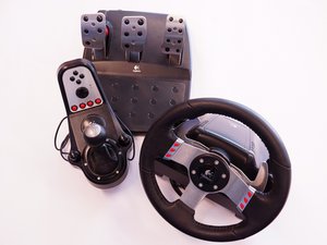
Same problem with G25.
Checked and works:
- power supply
- Motor (one looks smoked)
- USB (Pedals and Shift Gear works)
Isn´t Working:
- Calibration dosn´t start
- Wheel dosn´t work
I think it is something between the big chip (should be a mikrocontroller) and the motor. The motor is not starting and until the calibration isn´t done, no data from the X-Axis will be send.
I have checked the resistors mentioned in the video. Both are fine. I will check the others later.
The cover was warm, when the wheel broke. So i will add a cooling.
I have repaired mine. After spending several days on just searching the Internet, i can say that there isn’t “the way” (see at the end) to repair this. For searching the error you should have a bit knowledge of electronics. The following is for G25, but should also be for G27 and G29. This is a collection of things that can be the reason the wheel is not working. You should check in the order i have written it.
- Check if you have a power supply, and check if it delivers the right voltage (24 V for G25). Without a power supply the DC motors can’t turn the wheel. Whithout turning the wheel, there is no calibration possible. Without calibration the padals, shifting and buttons are working, but the wheel (X Axis) isn’t working.
- If the wheel starts turning for ~ 0,1 Second, then the power delivery and the motor driving circuits are fine. There are good possibilities, that the encoder isn’t working. The encoder is under the black plastic cover on one of the two DC motors. But you have to dissassemble the whole wheel. If the encoder is loose, then fix it. If it isn’t loose, then search for replacement. There are several descriptions and videos in the internet. Search for G25/G27 Encoder.
- If power is good, but nothing happens, check the fuse and the big resistors. If Voltage is fine go to the next point.
- If nothing happens, but there is Voltage after the big resistor (maybe you need more force to turn the wheel), check the MOSFETs. These are the two 8 leg SOICs on the top of the circuit. Below the connectors of the motors. Measure the electrical resistance between the legs. If i remember correct, then it should be around 1,4 MOhm. If it is below, replace it. But be careful, some legs are connectet internal and over the PCB. For the checking and replacement you should have a bit knowledge about electronics, MOSFETs and SMD soldering. By the way, you don’t have to use the same. I have used stronger ones with the same pinout. Measure again after you have done the replacement and write it down (See next point).
- If the mosfets are burned the second time and maybe the wheel is calibrating in one direction but not in the second or you need more force to pull it in one direction and less force for the other direction, check if you have replaced both mosfets. If one of the MOSFETs is damaged it will kill the second one. Because one is connected to +24 V and the second to GND. Each MOSFET has 2 channels. One channel of both mosfets are connected together and are connected to one wire of the DC motor. The second channel to the second wire. So the motors can turn in both directions. If one MOSFET fails, the seond one is connecting 24 V to GND…. ouch.
- If both MOSFETs were replaced and burned a third time, check the DC motors. Disconnect them and measure there electrical and mechanical resistance. Try them on ~ 3 - 5 V. On one of mine the bearing was stucked, so the MOSFETs were overloaded. Some cleaning, a drop of oil and some MOSFETs later it works.
- If both MOSFETs were replaced and burned a third time, but it isn’t the motor, check the big diodes between the motor connectors and the mosfets.
- I have also read about a thin coal surface from the coals of the DC motors, that shorten the MOSFETs. Open the motors and clean it.
- There is also a video on the red video plattform, showing a guy replacing some resistors.
- …
- Coolingmod is strongly recommended.
Maybe some one can translate it in a better english than mine.
Rdini: Can be the MOSFETs
Dodger 76: Can be the motors
Luca Weltert: 41.6 V sounds strange. G25 is 24 V. Maybe G27 or G29 uses 48 V and the 41,6 V are to low.
Sugar Bomb: You can’t calibrate it manual. If the encoder fails (~ 0,1 s) the calibration is stopped. Like you have found out: You need a power supply.
Magnus Buinevits: Can be the Encoder.
So this is not the same problem. I think every one of your G25/G27/G29 has a diffrent problem.

 2
2  2
2  1
1 


1 comentário
Hi yeah I'm using a g27 steering wheel. It was not used for 2 years and recently I started using it. The first time i turned the steering wheel it calibrated one way but not the other way and the LED light in the steering wheel blinked. This time it was working. The next day when i turned it on everything except the steering wheel was working. The LED did not blink, the steering wheel was not calibrating when it was turned on. And I also noticed two things the power notifying green LED light near the gear is turned on and dim when only the usb is connected to device. The next thing was the charger. when I just turn on the charger LED in it turns on green but when I connect it to steering wheel it goes off. So I tried a new charger, but the result is same. Is there anything I should do?
por DEONE SABU KURIAN